Administration Guide
- About This Guide
- I Installation, Setup and Upgrade
- II Configuration and Administration
- 6 Configuration and Administration Basics
- 7 Configuring and Managing Cluster Resources with Hawk2
- 8 Configuring and Managing Cluster Resources (Command Line)
- 9 Adding or Modifying Resource Agents
- 10 Fencing and STONITH
- 11 Storage Protection and SBD
- 12 Access Control Lists
- 13 Network Device Bonding
- 14 Load Balancing
- 15 Geo Clusters (Multi-Site Clusters)
- 16 Executing Maintenance Tasks
- III Storage and Data Replication
- IV Appendix
- Glossary
- E GNU Licenses
21 Cluster Logical Volume Manager (cLVM) #
Abstract#
When managing shared storage on a cluster, every node must be informed about changes that are done to the storage subsystem. The Logical Volume Manager 2 (LVM2), which is widely used to manage local storage, has been extended to support transparent management of volume groups across the whole cluster. Clustered volume groups can be managed using the same commands as local storage.
21.1 Conceptual Overview #
Clustered LVM2 is coordinated with different tools:
- Distributed Lock Manager (DLM)
Coordinates disk access for cLVM and mediates metadata access through locking.
- Logical Volume Manager2 (LVM2)
Enables flexible distribution of one file system over several disks. LVM2 provides a virtual pool of disk space.
- Clustered Logical Volume Manager (cLVM)
Coordinates access to the LVM2 metadata so every node knows about changes. cLVM does not coordinate access to the shared data itself; to enable cLVM to do so, you must configure OCFS2 or other cluster-aware applications on top of the cLVM-managed storage.
21.2 Configuration of cLVM #
Depending on your scenario it is possible to create a RAID 1 device with cLVM with the following layers:
LVM2. This is a very flexible solution if you want to increase or decrease your file system size, add more physical storage, or create snapshots of your file systems. This method is described in Section 21.2.3, “Scenario: cLVM with iSCSI on SANs”.
DRBD. This solution only provides RAID 0 (striping) and RAID 1 (mirroring). The last method is described in Section 21.2.4, “Scenario: cLVM With DRBD”.
Make sure you have fulfilled the following prerequisites:
A shared storage device is available, such as provided by a Fibre Channel, FCoE, SCSI, iSCSI SAN, or DRBD*.
In case of DRBD, both nodes must be primary (as described in the following procedure).
Check if the locking type of LVM2 is cluster-aware. The keyword
locking_typein/etc/lvm/lvm.confmust contain the value3(the default is1). Copy the configuration to all nodes, if necessary.Check if the
lvmetaddaemon is disabled, because it cannot work with cLVM. In/etc/lvm/lvm.conf, the keyworduse_lvmetadmust be set to0(the default is1). Copy the configuration to all nodes, if necessary.
21.2.1 Creating the Cluster Resources #
Preparing the cluster for use of cLVM includes the following basic steps:
Procedure 21.1: Creating a DLM Resource #
Start a shell and log in as
root.Check the current configuration of the cluster resources:
root #crm configure showIf you have already configured a DLM resource (and a corresponding base group and base clone), continue with Procedure 21.2, “Configuring DLM, CLVM, and STONITH”.
Otherwise, configure a DLM resource and a corresponding base group and base clone as described in Procedure 17.1, “Configuring a Base Group for DLM”.
Leave the crm live configuration with
exit.
21.2.2 Scenario: Configuring Cmirrord #
To track mirror log information in a cluster, the
cmirrord daemon is used. Cluster
mirrors are not possible without this daemon running.
We assume that /dev/sda and
/dev/sdb are the shared storage devices as with
DRBD, iSCSI, and others. Replace these with your own device name(s), if
necessary. Proceed as follows:
Procedure 21.2: Configuring DLM, CLVM, and STONITH #
Create a cluster with at least two nodes as described in Installation and Setup Quick Start.
Configure your cluster to run
dlm,clvmd, and STONITH:root #crmconfigurecrm(live)configure#primitiveclvmd ocf:heartbeat:clvm \ params with_cmirrord=1 \ op stop interval=0 timeout=100 \ op start interval=0 timeout=90 \ op monitor interval=20 timeout=20crm(live)configure#primitivedlm ocf:pacemaker:controld \ op start timeout="90" \ op stop timeout="100" \ op monitor interval="60" timeout="60"crm(live)configure#primitivesbd_stonith stonith:external/sbd \ params pcmk_delay_max=30crm(live)configure#groupg-storage dlm clvmdcrm(live)configure#clonecl-storage g-storage \ meta interleave="true" ordered=trueLeave crmsh with
exitand commit your changes.
Continue configuring your disks with Procedure 21.3.
Procedure 21.3: Configuring the Disks for cLVM #
Create a clustered volume group (VG):
root #pvcreate/dev/sda /dev/sdbroot #vgcreate-cy vg1 /dev/sda /dev/sdbCreate a mirrored-log logical volume (LV) in your cluster:
root #lvcreate-n lv1 -m1 -l10%VG vg1 --mirrorlog mirroredUse
lvsto show the progress. If the percentage number has reached 100%, the mirrored disk is successfully synchronized.To test the clustered volume
/dev/vg1/lv1, use the following steps:Read or write to
/dev/vg1/lv1.Deactivate your LV with
lvchange-an.Activate your LV with
lvchange-ay.Use
lvconvertto convert a mirrored log to a disk log.
Create a mirrored-log LV in another cluster VG. This is a different volume group from the previous one.
The current cLVM can only handle one physical volume (PV) per mirror
side. If one mirror is actually made up of several PVs that need to be
concatenated or striped, lvcreate does not understand
this. For this reason, lvcreate and
cmirrord metadata needs to understand
“grouping” of PVs into one side, effectively supporting
RAID10.
To support RAID10 for cmirrord,
use the following procedure (assuming that /dev/sda,
/dev/sdb, /dev/sdc, and
/dev/sdd are the shared storage devices):
Create a volume group (VG):
root #pvcreate/dev/sda /dev/sdb /dev/sdc /dev/sdd Physical volume "/dev/sda" successfully created Physical volume "/dev/sdb" successfully created Physical volume "/dev/sdc" successfully created Physical volume "/dev/sdd" successfully createdroot #vgcreatevgtest /dev/sda /dev/sdb /dev/sdc /dev/sdd Clustered volume group "vgtest" successfully createdOpen the file
/etc/lvm/lvm.confand go to the sectionallocation. Set the following line and save the file:mirror_logs_require_separate_pvs = 1
Add your tags to your PVs:
root #pvchange--addtag @a /dev/sda /dev/sdbroot #pvchange--addtag @b /dev/sdc /dev/sddA tag is an unordered keyword or term assigned to the metadata of a storage object. Tagging allows you to classify collections of LVM2 storage objects in ways that you find useful by attaching an unordered list of tags to their metadata.
List your tags:
root #pvs-o pv_name,vg_name,pv_tags /dev/sd{a,b,c,d}You should receive this output:
PV        VG   PV Tags
/dev/sda  vgtest   a
/dev/sdb  vgtest   a
/dev/sdc  vgtest   b
/dev/sdd  vgtest   b
If you need further information regarding LVM2, refer to the SUSE Linux Enterprise Server 12 SP5 Storage Administration Guide: https://documentation.suse.com/sles-12/html/SLES-all/cha-lvm.html.
21.2.3 Scenario: cLVM with iSCSI on SANs #
The following scenario uses two SAN boxes which export their iSCSI targets to several clients. The general idea is displayed in Figure 21.1, “Setup of iSCSI with cLVM”.
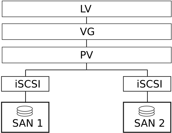
Figure 21.1: Setup of iSCSI with cLVM #
Warning: Data Loss
The following procedures will destroy any data on your disks!
Configure only one SAN box first. Each SAN box needs to export its own iSCSI target. Proceed as follows:
Procedure 21.4: Configuring iSCSI Targets (SAN) #
Run YaST and click › to start the iSCSI Server module.
If you want to start the iSCSI target whenever your computer is booted, choose , otherwise choose .
If you have a firewall running, enable .
Switch to the tab. If you need authentication enable incoming or outgoing authentication or both. In this example, we select .
Add a new iSCSI target:
Switch to the tab.
Click .
Enter a target name. The name needs to be formatted like this:
iqn.DATE.DOMAIN
For more information about the format, refer to Section 3.2.6.3.1. Type "iqn." (iSCSI Qualified Name) at http://www.ietf.org/rfc/rfc3720.txt.
If you want a more descriptive name, you can change it as long as your identifier is unique for your different targets.
Click .
Enter the device name in and use a .
Click twice.
Confirm the warning box with .
Open the configuration file
/etc/iscsi/iscsid.confand change the parameternode.startuptoautomatic.
Now set up your iSCSI initiators as follows:
Procedure 21.5: Configuring iSCSI Initiators #
Run YaST and click › .
If you want to start the iSCSI initiator whenever your computer is booted, choose , otherwise set .
Change to the tab and click the button.
Add your IP address and your port of your iSCSI target (see Procedure 21.4, “Configuring iSCSI Targets (SAN)”). Normally, you can leave the port as it is and use the default value.
If you use authentication, insert the incoming and outgoing user name and password, otherwise activate .
Select . The found connections are displayed in the list.
Proceed with .
Open a shell, log in as
root.Test if the iSCSI initiator has been started successfully:
root #iscsiadm-m discovery -t st -p 192.168.3.100 192.168.3.100:3260,1 iqn.2010-03.de.jupiter:san1Establish a session:
root #iscsiadm-m node -l -p 192.168.3.100 -T iqn.2010-03.de.jupiter:san1 Logging in to [iface: default, target: iqn.2010-03.de.jupiter:san1, portal: 192.168.3.100,3260] Login to [iface: default, target: iqn.2010-03.de.jupiter:san1, portal: 192.168.3.100,3260]: successfulSee the device names with
lsscsi:... [4:0:0:2] disk IET ... 0 /dev/sdd [5:0:0:1] disk IET ... 0 /dev/sde
Look for entries with
IETin their third column. In this case, the devices are/dev/sddand/dev/sde.
Procedure 21.6: Creating the LVM2 Volume Groups #
Open a
rootshell on one of the nodes you have run the iSCSI initiator from Procedure 21.5, “Configuring iSCSI Initiators”.Prepare the physical volume for LVM2 with the command
pvcreateon the disks/dev/sddand/dev/sde:root #pvcreate/dev/sddroot #pvcreate/dev/sdeCreate the cluster-aware volume group on both disks:
root #vgcreate--clustered y clustervg /dev/sdd /dev/sdeCreate logical volumes as needed:
root #lvcreate-m1 --name clusterlv --size 500M clustervgCheck the physical volume with
pvdisplay:--- Physical volume --- PV Name /dev/sdd VG Name clustervg PV Size 509,88 MB / not usable 1,88 MB Allocatable yes PE Size (KByte) 4096 Total PE 127 Free PE 127 Allocated PE 0 PV UUID 52okH4-nv3z-2AUL-GhAN-8DAZ-GMtU-Xrn9Kh --- Physical volume --- PV Name /dev/sde VG Name clustervg PV Size 509,84 MB / not usable 1,84 MB Allocatable yes PE Size (KByte) 4096 Total PE 127 Free PE 127 Allocated PE 0 PV UUID Ouj3Xm-AI58-lxB1-mWm2-xn51-agM2-0UuHFCCheck the volume group with
vgdisplay:--- Volume group --- VG Name clustervg System ID Format lvm2 Metadata Areas 2 Metadata Sequence No 1 VG Access read/write VG Status resizable Clustered yes Shared no MAX LV 0 Cur LV 0 Open LV 0 Max PV 0 Cur PV 2 Act PV 2 VG Size 1016,00 MB PE Size 4,00 MB Total PE 254 Alloc PE / Size 0 / 0 Free PE / Size 254 / 1016,00 MB VG UUID UCyWw8-2jqV-enuT-KH4d-NXQI-JhH3-J24anD
After you have created the volumes and started your resources you should
have a new device named
/dev/dm-*.
It is recommended to use a clustered file system on top of your LVM2
resource, for example OCFS. For more information, see
Chapter 18, OCFS2.
21.2.4 Scenario: cLVM With DRBD #
The following scenarios can be used if you have data centers located in different parts of your city, country, or continent.
Procedure 21.7: Creating a Cluster-Aware Volume Group With DRBD #
Create a primary/primary DRBD resource:
First, set up a DRBD device as primary/secondary as described in Procedure 20.1, “Manually Configuring DRBD”. Make sure the disk state is
up-to-dateon both nodes. Check this withdrbdadm status.Add the following options to your configuration file (usually something like
/etc/drbd.d/r0.res):resource r0 { net { allow-two-primaries; } ... }Copy the changed configuration file to the other node, for example:
root #scp/etc/drbd.d/r0.res venus:/etc/drbd.d/Run the following commands on both nodes:
root #drbdadmdisconnect r0root #drbdadmconnect r0root #drbdadmprimary r0Check the status of your nodes:
root #drbdadmstatus r0
Include the clvmd resource as a clone in the pacemaker configuration, and make it depend on the DLM clone resource. See Procedure 21.1, “Creating a DLM Resource” for detailed instructions. Before proceeding, confirm that these resources have started successfully on your cluster. You may use
crm statusor the Web interface to check the running services.Prepare the physical volume for LVM2 with the command
pvcreate. For example, on the device/dev/drbd_r0the command would look like this:root #pvcreate/dev/drbd_r0Create a cluster-aware volume group:
root #vgcreate--clustered y myclusterfs /dev/drbd_r0Create logical volumes as needed. You may probably want to change the size of the logical volume. For example, create a 4 GB logical volume with the following command:
root #lvcreate-m1 --name testlv -L 4G myclusterfsThe logical volumes within the VG are now available as file system mounts or raw usage. Ensure that services using them have proper dependencies to collocate them with and order them after the VG has been activated.
After finishing these configuration steps, the LVM2 configuration can be done like on any stand-alone workstation.
21.3 Configuring Eligible LVM2 Devices Explicitly #
When several devices seemingly share the same physical volume signature (as can be the case for multipath devices or DRBD), it is recommended to explicitly configure the devices which LVM2 scans for PVs.
For example, if the command vgcreate uses the physical
device instead of using the mirrored block device, DRBD will be confused
which may result in a split brain condition for DRBD.
To deactivate a single device for LVM2, do the following:
Edit the file
/etc/lvm/lvm.confand search for the line starting withfilter.The patterns there are handled as regular expressions. A leading “a” means to accept a device pattern to the scan, a leading “r” rejects the devices that follow the device pattern.
To remove a device named
/dev/sdb1, add the following expression to the filter rule:"r|^/dev/sdb1$|"
The complete filter line will look like the following:
filter = [ "r|^/dev/sdb1$|", "r|/dev/.*/by-path/.*|", "r|/dev/.*/by-id/.*|", "a/.*/" ]
A filter line, that accepts DRBD and MPIO devices but rejects all other devices would look like this:
filter = [ "a|/dev/drbd.*|", "a|/dev/.*/by-id/dm-uuid-mpath-.*|", "r/.*/" ]
Write the configuration file and copy it to all cluster nodes.
21.4 For More Information #
Thorough information is available from the pacemaker mailing list, available at http://www.clusterlabs.org/wiki/Help:Contents.
The official cLVM FAQ can be found at http://sources.redhat.com/cluster/wiki/FAQ/CLVM.