3 Cloud Lifecycle Manager Admin UI User Guide #
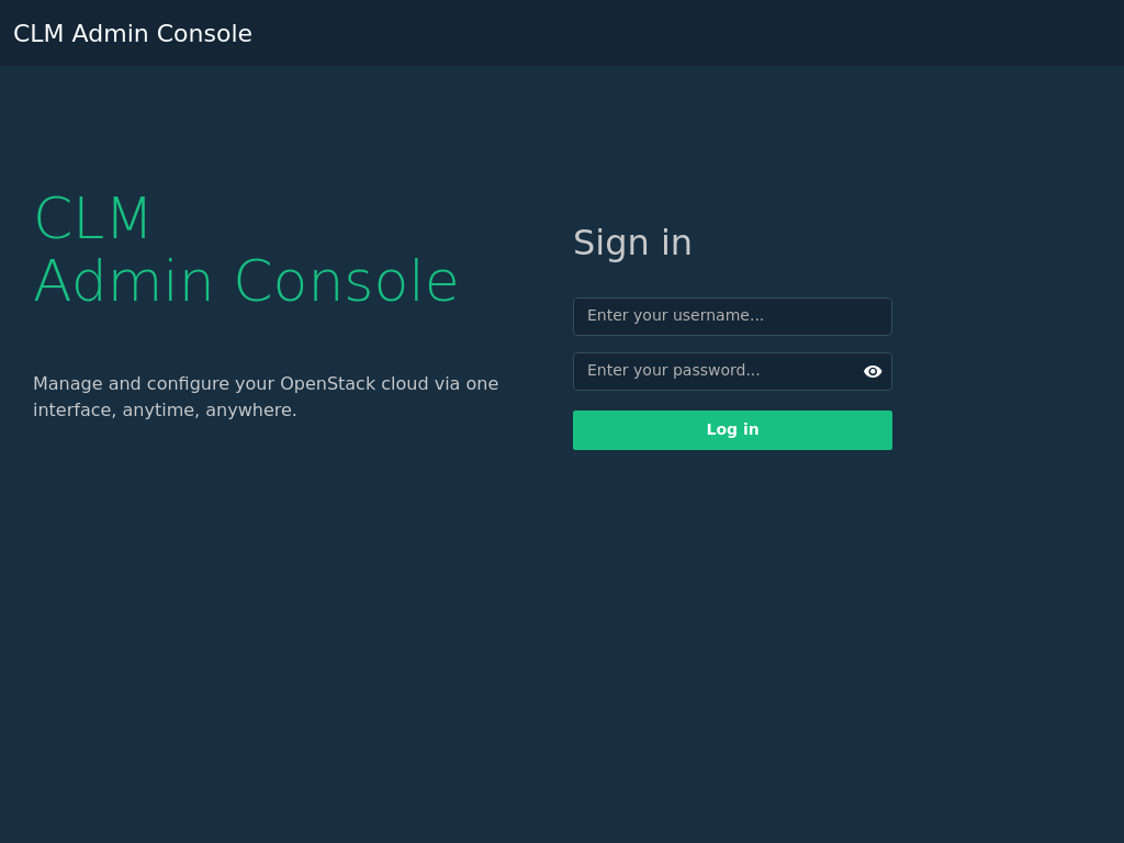
The Cloud Lifecycle Manager Admin UI is a web-based GUI for viewing and managing the
configuration of an installed cloud. After successfully deploying the cloud
with the Install UI, the final screen displays a link to the CLM Admin UI.
(For example, see Figure 21.1, “Cloud Deployment Successful”). Usually the URL
associated with this link is
https://DEPLOYER_MGMT_NET_IP:9085,
although it may be different depending on the cloud configuration and the
installed version of SUSE OpenStack Cloud.
3.1 Accessing the Admin UI #
In a browser, go to
https://DEPLOYER_MGMT_NET_IP:9085.
The
DEPLOYER_MGMT_NET_IP:PORT_NUMBER
is not necessarily the same for all installations, and can be displayed with
the following command:
ardana > openstack endpoint list --service ardana --interface admin -c URLAccessing the Cloud Lifecycle Manager Admin UI requires access to the MANAGEMENT network that was configured when the Cloud was deployed. Access to this network is necessary to be able to access the Cloud Lifecycle Manager Admin UI and log in. Depending on the network setup, it may be necessary to use an SSH tunnel similar to what is recommended in Section 21.5, “Running the Install UI”. The Admin UI requires keystone and HAProxy to be running and to be accesible. If keystone or HAProxy are not running, cloud reconfiguration is limited to the command line.
Logging in requires a keystone user. If the user is not an admin on the default domain and one or more projects, the Cloud Lifecycle Manager Admin UI will not display information about the Cloud and may present errors.
3.2 Admin UI Pages #
3.2.1 Services #
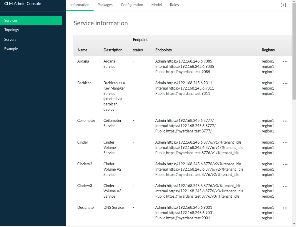
Services pages relay information about the various OpenStack and other
services that have been deployed as part of the cloud. Service information
displays the list of services registered with keystone and the endpoints
associated with those services. The information is equivalent to running
the command openstack endpoint list.
The Service Information table contains the following
information, based on how the service is registered with keystone:
- Name
The name of the service, this may be an OpenStack code name
- Description
Service description, for some services this is a repeat of the name
- Endpoints
Services typically have 1 or more endpoints that are accessible to make API calls. The most common configuration is for a service to have
Admin,Public, andInternalendpoints, with each intended for access by consumers corresponding to the type of endpoint.- Region
Service endpoints are part of a region. In multi-region clouds, some services will have endpoints in multiple regions.
3.2.2 Packages #
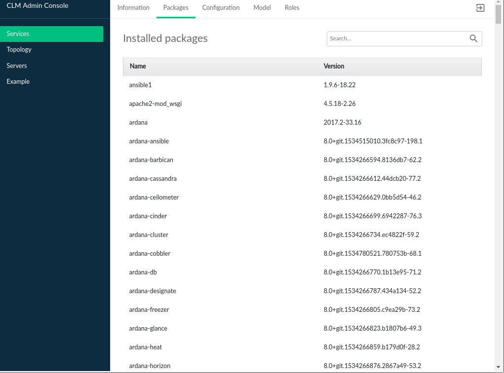
The tab displays packages that are part of the SUSE OpenStack Cloud product.
The SUSE Cloud Packages table contains the following:
- Name
The name of the SUSE Cloud package
- Version
The version of the package which is installed in the Cloud
Packages with the venv- prefix denote the version of
the specific OpenStack package that is deployed. The release name can be
determined from the OpenStack Releases
page.
3.2.3 Configuration #
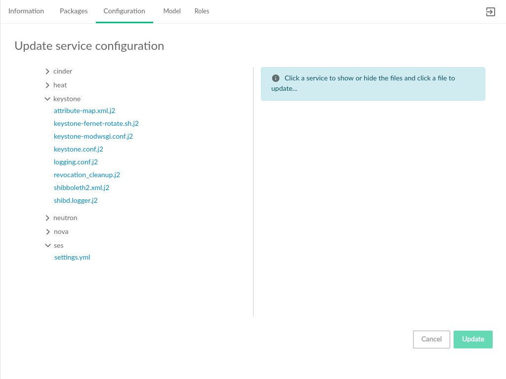
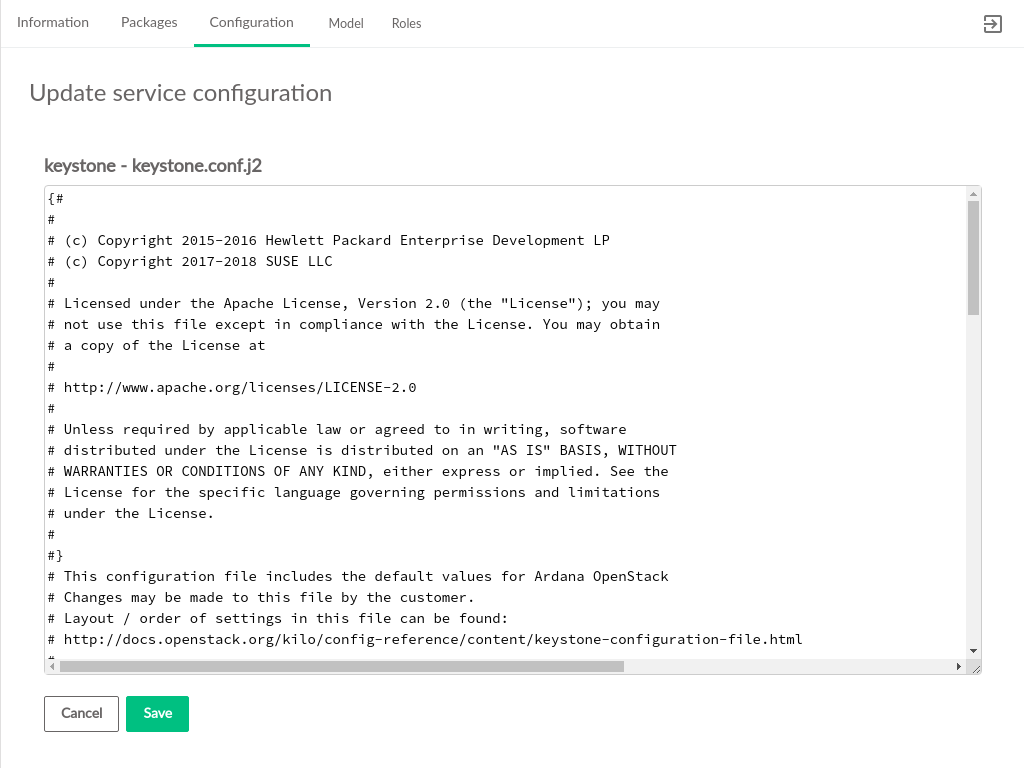
The tab displays services that are
deployed in the cloud and the configuration files associated with those
services. Services may be reconfigured by editing the
.j2 files listed and clicking the
button.
This page also provides the ability to set up SUSE Enterprise Storage Integration after initial deployment.
Clicking one of the listed configuration files opens the file editor where changes can be made. Asterisks identify files that have been edited but have not had their updates applied to the cloud.
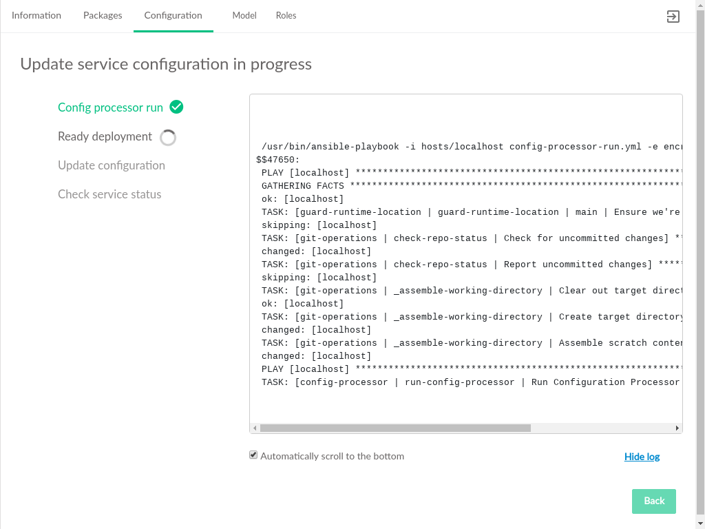
After editing the service configuration, click the button to begin deploying configuration changes to the cloud. The status of those changes will be streamed to the UI.
Configure SUSE Enterprise Storage After Initial Deployment
A link to the settings.yml file is available under the
ses selection on the tab.
To set up SUSE Enterprise Storage Integration:
Click on the link to edit the
settings.ymlfile.Uncomment the
ses_config_pathparameter, specify the location on the deployer host containing theses_config.ymlfile, and save thesettings.ymlfile.If the
ses_config.ymlfile does not yet exist in that location on the deployer host, a new link will appear for uploading a file from your local workstation.When
ses_config.ymlis present on the deployer host, it will appear in thesessection of the tab and can be edited directly there.
If the cloud is configured using self-signed certificates, the streaming status updates (including the log) may be interupted and require a reload of the CLM Admin UI. See Section 8.2, “TLS Configuration” for details on using signed certificates.
3.2.4 Model #
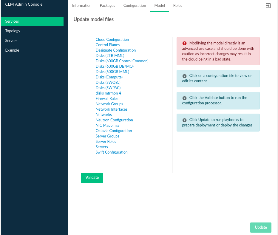
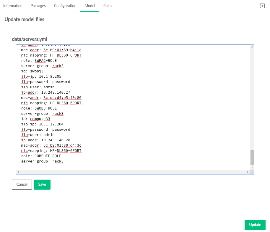
The tab displays input models that are deployed in the cloud and the associated model files. The model files listed can be modified.
Clicking one of the listed model files opens the file editor where changes can be made. Asterisks identify files that have been edited but have not had their updates applied to the cloud.
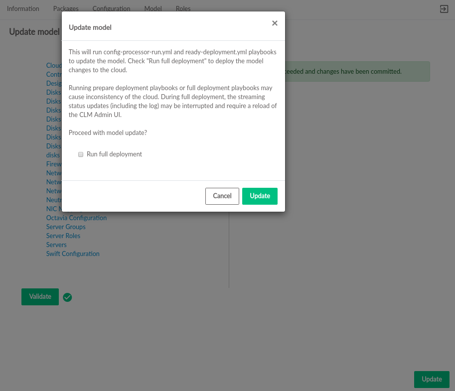
After editing the model file, click the button
to validate changes. If validation is successful,
is enabled. Click the button to deploy the
changes to the cloud. Before starting deployment, a confirmation dialog
shows the choices of only running
config-processor-run.yml and
ready-deployment.yml playbooks or running a full
deployment. It also indicates the risk of updating the deployed cloud.
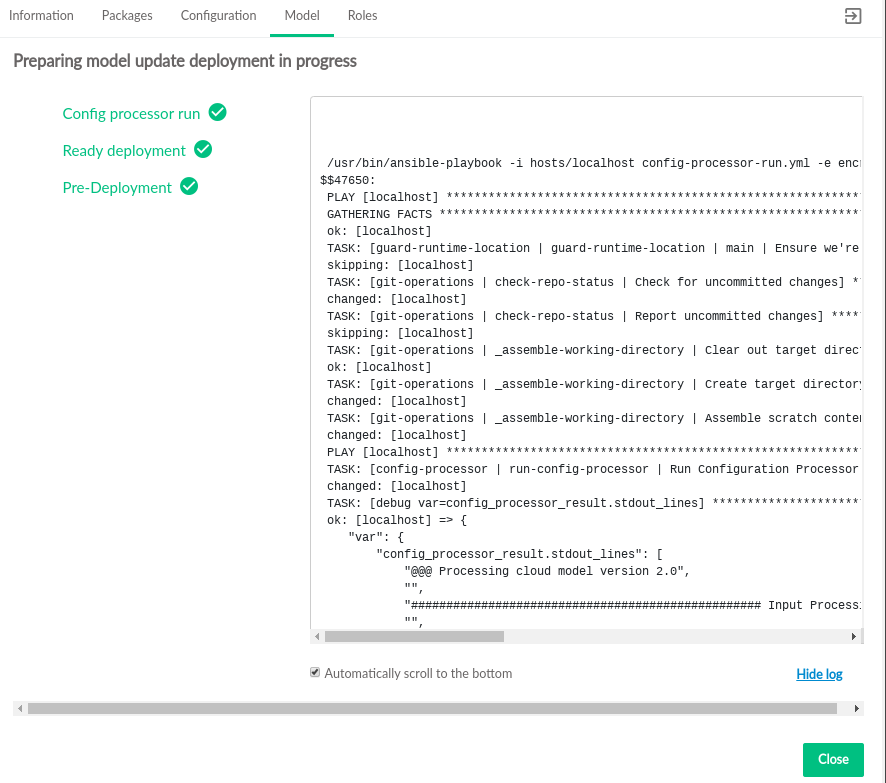
Click to start deployment. The status of the changes will be streamed to the UI.
If the cloud is configured using self-signed certificates, the streaming status updates (including the log) may be interrupted. The CLM Admin UI must be reloaded. See Section 8.2, “TLS Configuration” for details on using signed certificates.
3.2.5 Roles #
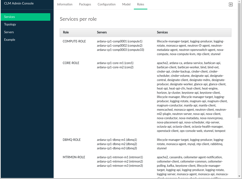
The tab displays the list of all roles that have been defined in the Cloud Lifecycle Manager input model, the list of servers that role, and the services installed on those servers.
The Services Per Role table contains the following:
- Role
The name of the role in the data model. In the included data model templates, these names are descriptive, such as
MTRMON-ROLEfor a metering and monitoring server. There is no strict constraint on role names and they may have been altered at install time.- Servers
The model IDs for the servers that have been assigned this role. This does not necessarily correspond to any DNS or other naming labels a host has, unless the host ID was set that way during install.
- Services
A list of OpenStack and other Cloud related services that comprise this role. Servers that have been assigned this role will have these services installed and enabled.
3.2.6 Servers #
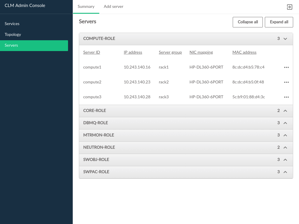
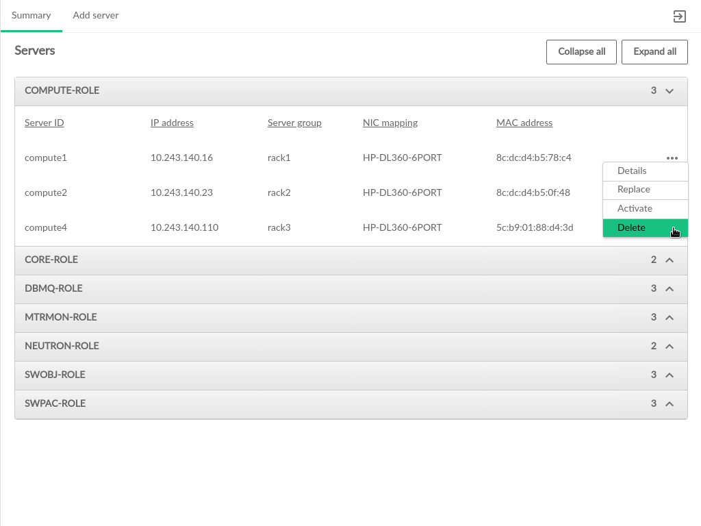
The pages contain information about the hardware that comprises the cloud, including the configuration of the servers, and the ability to add new compute nodes to the cloud.
The Servers table contains the following information:
- ID
This is the ID of the server in the data model. This does not necessarily correspond to any DNS or other naming labels a host has, unless the host ID was set that way during install.
- IP Address
The management network IP address of the server
- Server Group
The server group which this server is assigned to
- NIC Mapping
The NIC mapping that describes the PCI slot addresses for the servers ethernet adapters
- Mac Address
The hardware address of the servers primary physical ethernet adapter
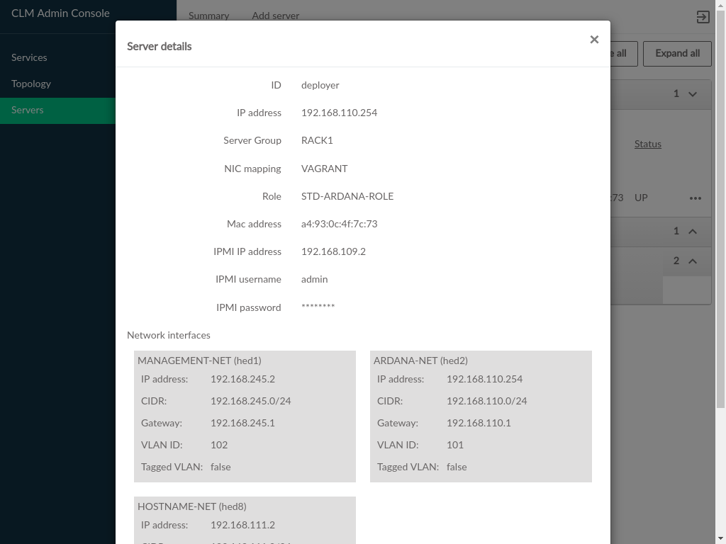
3.2.7 Admin UI Server Details #
Server Details can be viewed by clicking the menu at the
right side of each row in the Servers table, the server
details dialog contains the information from the Servers table and the
following additional fields:
- IPMI IP Address
The IPMI network address, this may be empty if the server was provisioned prior to being added to the Cloud
- IPMI Username
The username that was specified for IPMI access
- IPMI Password
This is obscured in the readonly dialog, but is editable when adding a new server
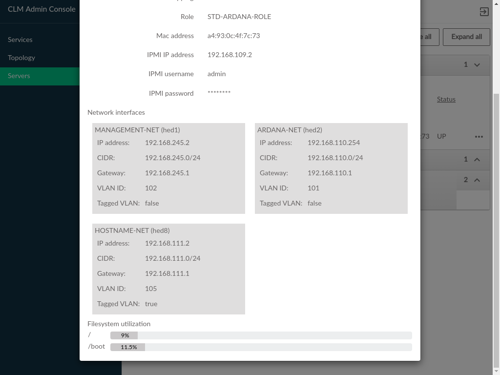
- Network Interfaces
The network interfaces configured on the server
- Filesystem Utilization
Filesystem usage (percentage of filesystem in use). Only available if monasca is in use
3.3 Topology #
The topology section of the Cloud Lifecycle Manager Admin UI displays an overview of how the Cloud is configured. Each section of the topology represents some facet of the Cloud configuration and provides a visual layout of the way components are associated with each other. Many of the components in the topology are linked to each other, and can be navigated between by clicking on any component that appears as a hyperlink.
3.3.1 Control Planes #
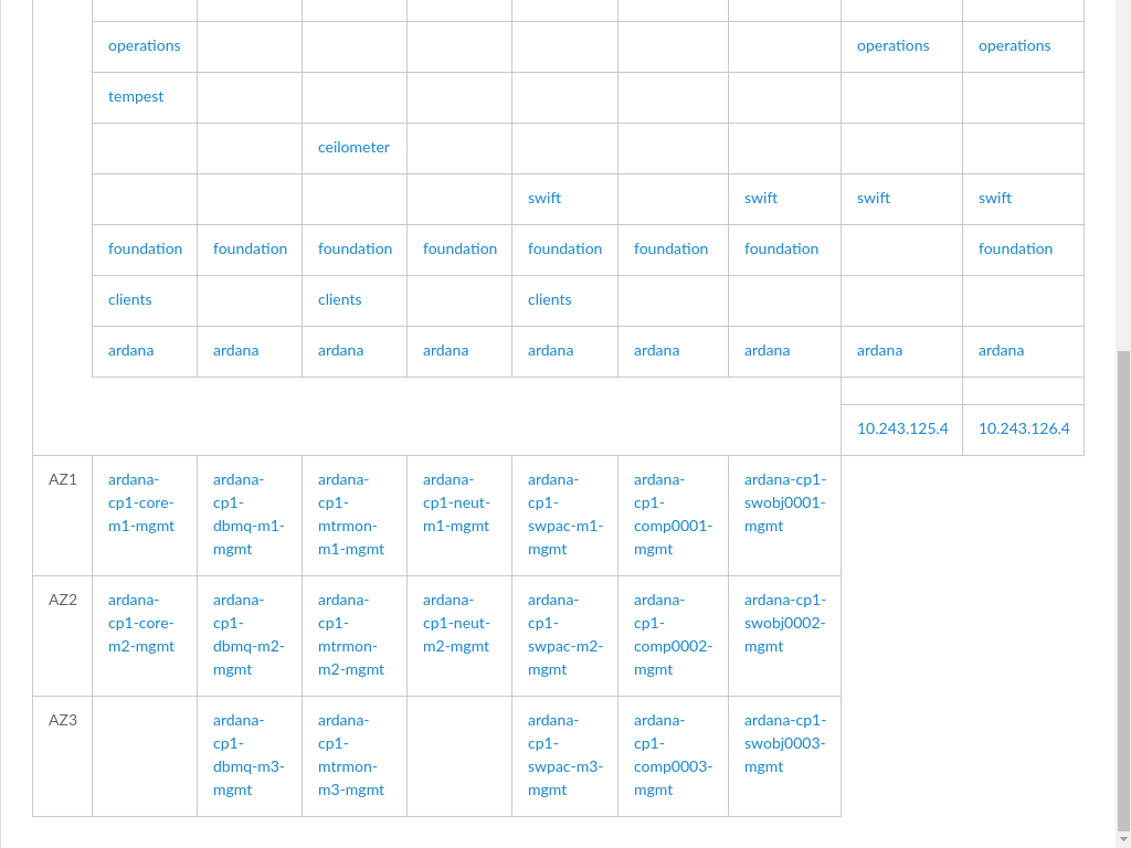
The tab displays control planes and availability zones within the Cloud.
Each control plane is show as a table of clusters, resources, and load balancers (represented by vertical columns in the table).
- Control Plane
A set of servers dedicated to running the infrastructure of the Cloud. Many Cloud configurations will have only a single control plane.
- Clusters
A set of one or more servers hosting a particular set of services, tied to the
rolethat has been assigned to that server.Clustersare generally differentiated fromResourcesin that they are fixed size groups of servers that do not grow as the Cloud grows.- Resources
Servers hosting the scalable parts of the Cloud, such as Compute Hosts that host VMs, or swift servers for object storage. These will vary in number with the size and scale of the Cloud and can generally be increased after the initial Cloud deployment.
- Load Balancers
Servers that distribute API calls across servers hosting the called services.
- Availability Zones
Listed beneath the running services, groups together in a row the hosts in a particular availability zone for a particular cluster or resource type (the rows are AZs, the columns are clusters/resources)
3.3.2 Regions #
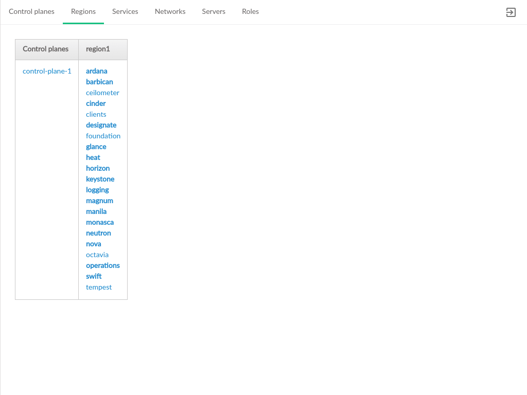
Displays the distribution of control plane services across regions. Clouds that have only a single region will list all services in the same cell.
- Control Planes
The group of services that run the Cloud infrastructure
- Region
Each region will be represented by a column with the region name as the column header. The list of services that are running in that region will be in that column, with each row corresponding to a particular control plane.
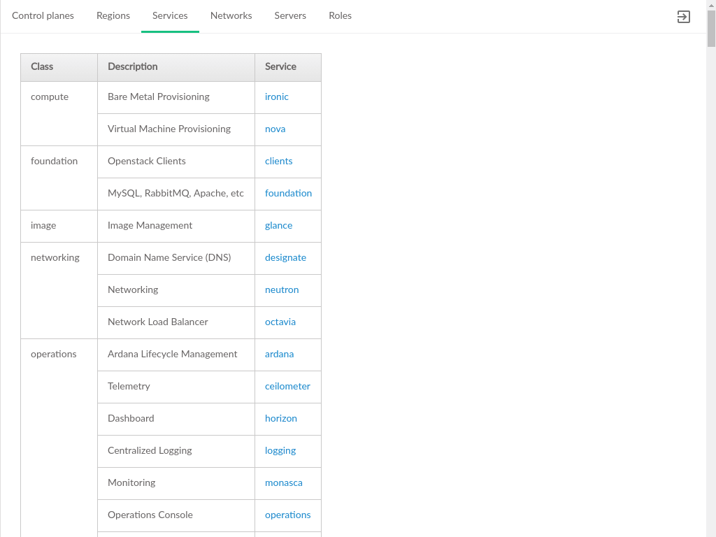
3.3.3 Services #
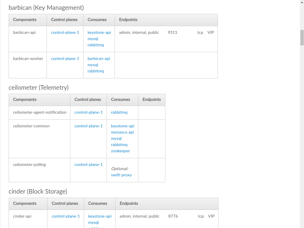
A list of services running in the Cloud, organized by the type (class) of service. Each service is then listed along with the control planes that the service is part of, the other services that each particular service consumes (requires), and the endpoints of the service, if the service exposes an API.
- Class
A category of like services, such as "security" or "operations". Multiple services may belong to the same category.
- Description
A short description of the service, typically sourced from the service itself
- Service
The name of the service. For OpenStack services, this is the project codename, such as nova for virtual machine provisioning. Clicking a service will navigate to the section of this page with details for that particular service.
The detail data about a service provides additional insight into the service, such as what other services are required to run a service, and what network protocols can be used to access the service
- Components
Each service is made up of one or more components, which are listed separately here. The components of a service may represent pieces of the service that run on different hosts, provide distinct functionality, or modularize business logic.
- Control Planes
A service may be running in multiple control planes. Each control plane that a service is running in will be listed here.
- Consumes
Other services required for this service to operate correctly.
- Endpoints
How a service can be accessed, typically a REST API, though other network protocols may be listed here. Services that do not expose an API or have any sort of external access will not list any entries here.
3.3.4 Networks #
Lists the networks and network groups that comprise the Cloud. Each network group is respresented by a row in the table, with columns identifying which networks are used by the intersection of the group (row) and cluster/resource (column).
- Group
The network group
- Clusters
A set of one or more servers hosting a particular set of services, tied to the
rolethat has been assigned to that server.Clustersare generally differentiated fromResourcesin that they are fixed size groups of servers that do not grow as the Cloud grows.- Resources
Servers hosting the scalable parts of the Cloud, such as Compute Hosts that host VMs, or swift servers for object storage. These will vary in number with the size and scale of the Cloud and can generally be increased after the initial Cloud deployment.
Cells in the middle of the table represent the network that is running on the resource/cluster represented by that column and is part of the network group identified in the leftmost column of the same row.
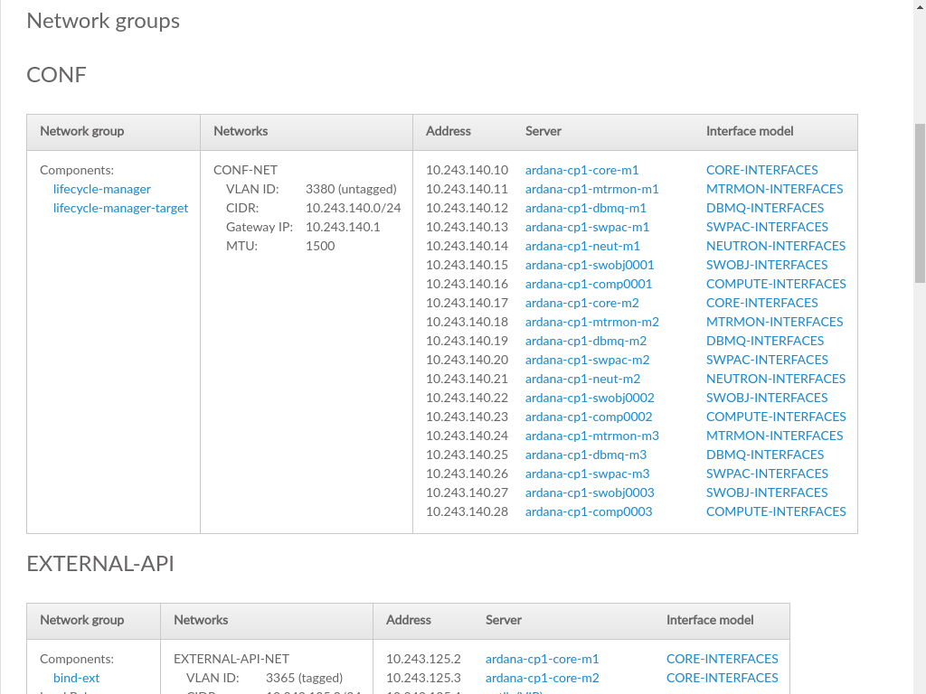
Each network group is listed along with the servers and interfaces that comprise the network group.
- Network Group
The elements that make up the network group, whose name is listed above the table
- Networks
Networks that are part of the specified network group
- Address
IP address of the corresponding server
- Server
Server name of the server that is part of this network. Clicking on a server will load the server topology details.
- Interface Model
The particular combination of hardware address and bonding that tie this server to the specified network group. Clicking on an
Interface
       Model
will load the corresponding section of theRolespage.
3.3.5 Servers #
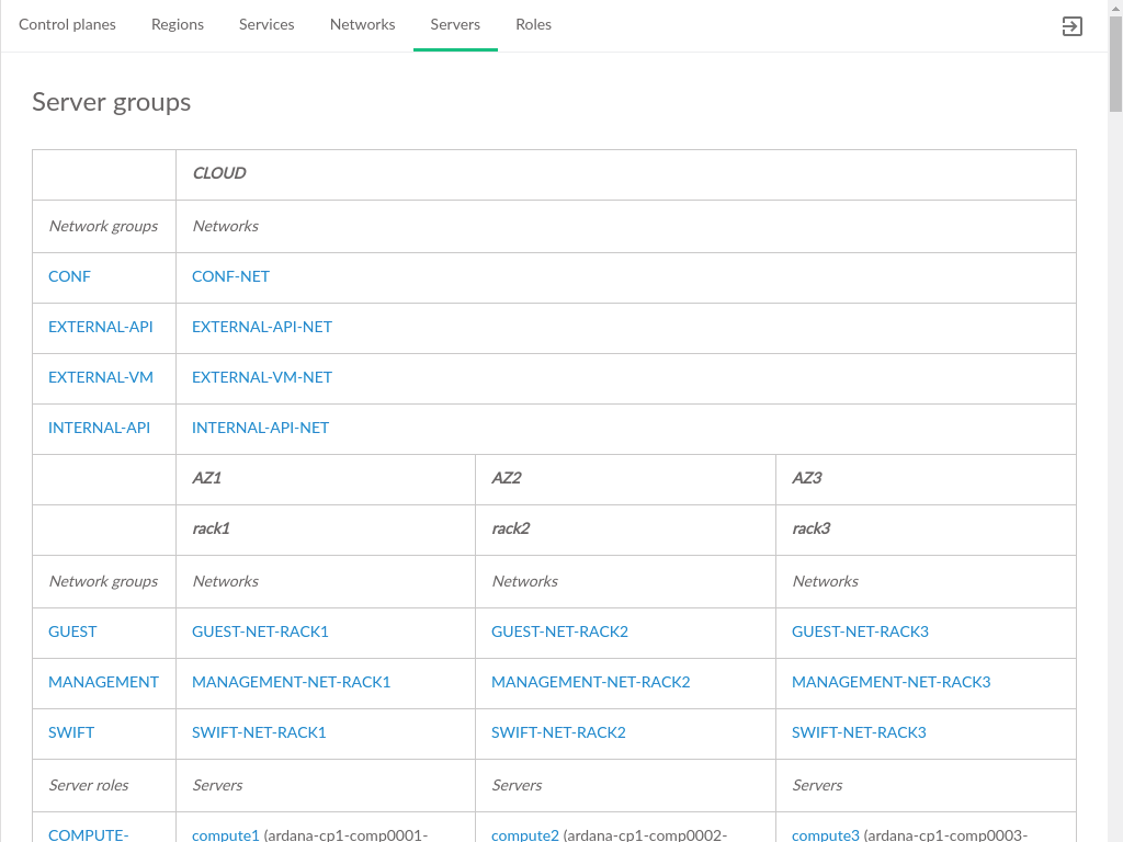
A hierarchical display of the tree of Server Groups. Groups will be
represented by a heading with their name, starting with the first row which
contains the Cloud-wide server group (often called
CLOUD). Within each Server Group, the Network Groups,
Networks, Servers, and Server Roles are broken down. Note that server groups
can be nested, producing a tree-like structure of groups.
- Network Groups
The network groups that are part of this server group.
- Networks
The network that is part of the server group and corresponds to the network group in the same row.
- Server Roles
The model defined role that was applied to the server, made up of a combination of services, and network/storage configurations unique to that role within the Cloud
- Servers
The servers that have the role defined in their row and are part of the network group represented by the column the server is in.
3.3.6 Roles #
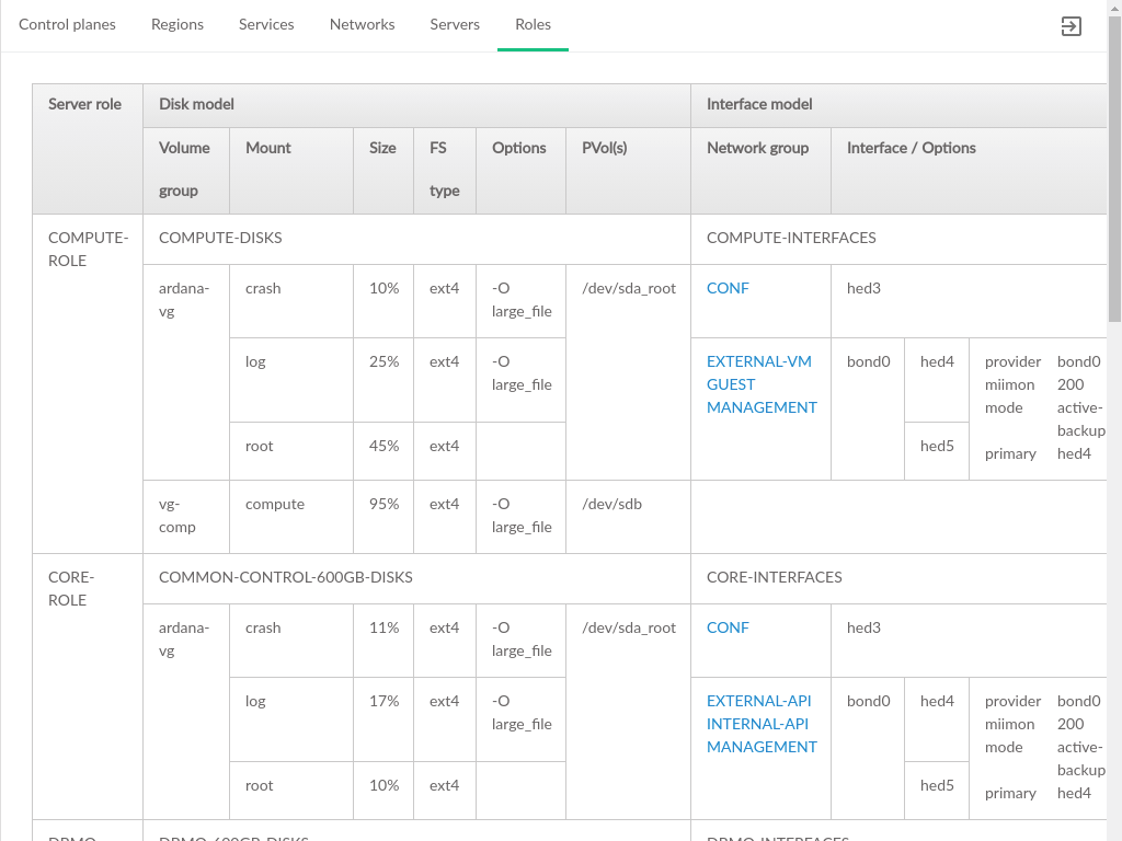
The list of server roles that define the server configurations for the Cloud. Each server role consists of several configurations. In this topology the focus is on the Disk Models and Network Interface Models that are applied to the servers with that role.
- Server Role
The name of the role, as it is defined in the model
- Disk Model
The name of the disk model
- Volume Group
Name of the volume group
- Mount
Name of the volume being mounted on the server
- Size
The size of the volume as a percentage of physical disk space
- FS Type
Filesystem type
- Options
Optional flags applied when mounting the volume
- PVol(s)
The physical address to the storage used for this volume group
- Interface Model
The name of the interface model
- Network Group
The name of the network group. Clicking on a Network Group will load the details of that group on the Networks page.
- Interface/Options
Includes logical network name, such as
hed1,hed2, andbondinformation grouping the logical network name together. The Cloud software will map these to physical devices.
3.4 Server Management #
3.4.1 Adding Servers #
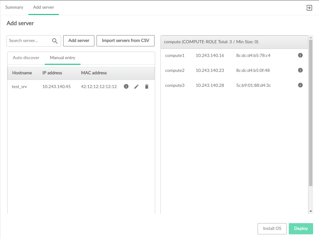
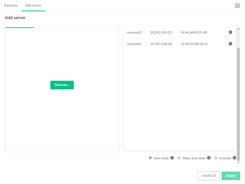
The Add Server page in the Cloud Lifecycle Manager Admin UI allows for adding additional Compute Nodes to the Cloud.
3.4.1.1 Available Servers #
Servers that can be added to the Cloud are shown on the left side of the
Add Server screen. Additional servers can be included in
this list three different ways:
Discover servers via SUSE Manager or HPE OneView (for details on adding servers via autodiscovery, see Section 21.4, “Optional: Importing Certificates for SUSE Manager and HPE OneView” and Section 21.5, “Running the Install UI”
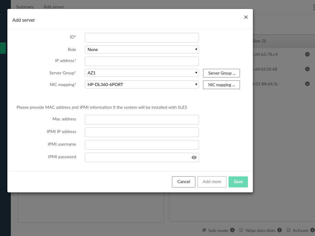
Manually add servers individually by clicking and filling out the form with the server information (instructions below)
Create a CSV file of the servers to be added (see Section 21.3, “Optional: Creating a CSV File to Import Server Data”)
Manually adding a server requires the following fields:
- ID
A unique name for the server
- IP Address
The IP address that the server has, or will have, in the Cloud
- Server Group
Which server group the server will belong to. The IP address must be compatible with the selected Server Group. If the required Server Group is not present, it can be created
- NIC Mapping
The NIC to PCI address mapping for the server being added to the Cloud. If the required NIC mapping is not present, it can be created
- Role
Which compute role to add the server to. If this is set, the server will be immediately assigned that role on the right side of the page. If it is not set, the server will be added to the left side panel of available servers
Some additional fields must be set if the server is not already provisioned with an OS, or if a new OS install is desired for the server. These fields are not required if an OpenStack Cloud compatible OS is already installed:
- MAC Address
The MAC address of the IPMI network card of the server
- IPMI IP Address
The IPMI network address (IP address) of the server
- IPMI Username
Username to log in to IPMI on the server
- IPMI Password
Password to log in to IPMI on the server
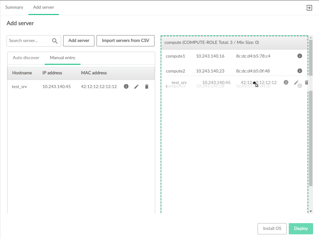
Servers in the available list can be dragged to the desired role on the right. Only Compute-related roles will be displayed.
3.4.1.2 Add Server Settings #
There are several settings that apply across all Compute Nodes being added to the Cloud. Beneath the list of nodes, users will find options to control whether existing nodes can be modified, whether the new nodes should have their data disks wiped, and whether to activate the new Compute Nodes as part of the update process.
- Safe Mode
Prevents modification of existing Compute Nodes. Can be unchecked to allow modifications. Modifying existing Compute Nodes has the potential to disrupt the continuous operation of the Cloud and should be done with caution.
- Wipe Data Disks
The data disks on the new server will not be wiped by default, but users can specify to wipe clean the data disks as part of the process of adding the Compute Node(s) to the Cloud.
- Activate
Activates the added Compute Node(s) during the process of adding them to the Cloud. Activation adds a Compute Node to the pool of nodes that the
nova-scheduleruses when instantiating VMs.
3.4.1.3 Install OS #
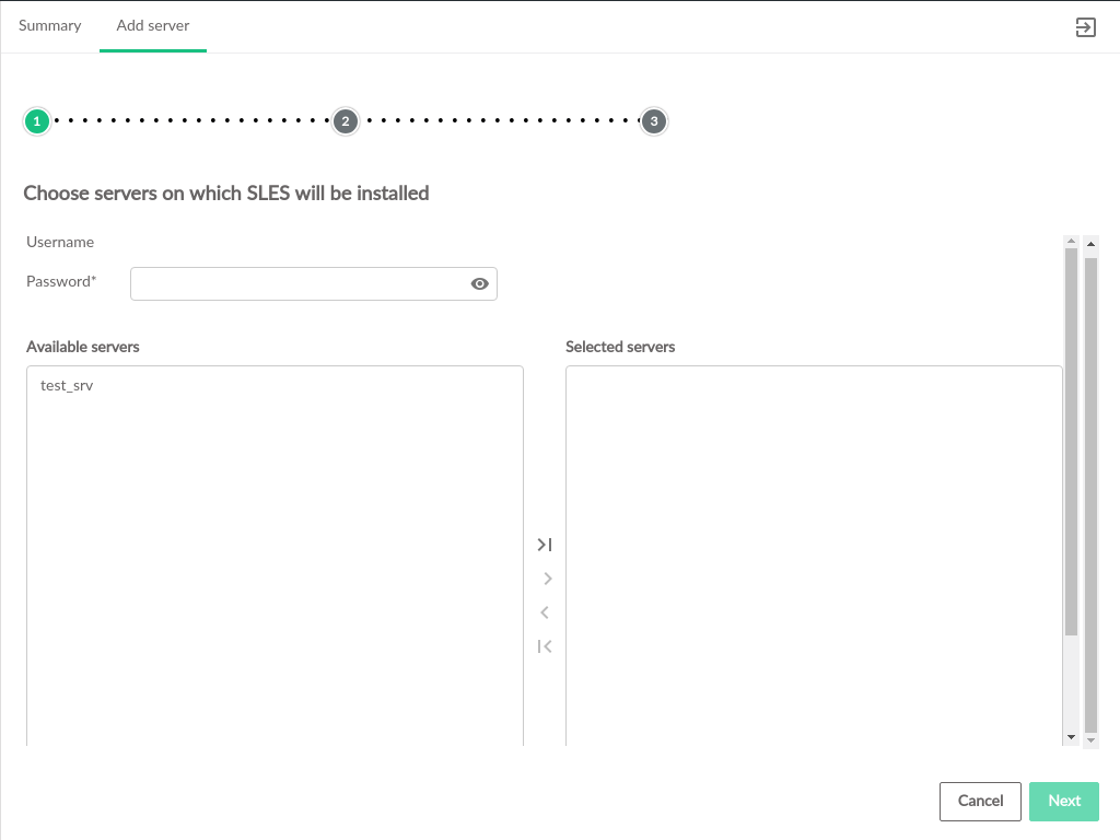
Servers that have been assigned a role but not yet deployed can have SLES installed as part of the Cloud deployment. This step is necessary for servers that are not provisioned with an OS.
On the Install OS page, the Available
Servers list will be populated with servers that have been
assigned to a role but not yet deployed to the Cloud. From here, select
which servers to install an OS onto and use the arrow controls to move them
to the Selected Servers box on the right. After all servers that require an
OS to be provisioned have been added to the Selected Servers list and click
.
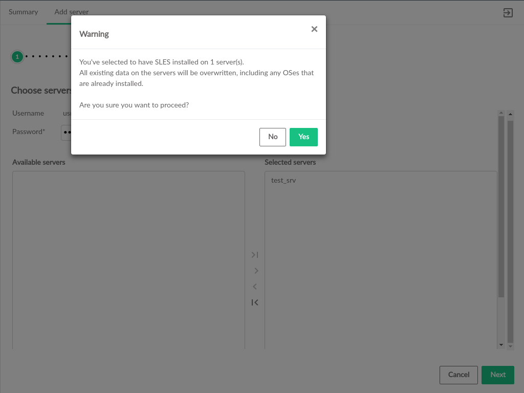
The UI will prompt for confirmation that the OS should be installed, because provisioning an OS will replace any existing operating system on the server.
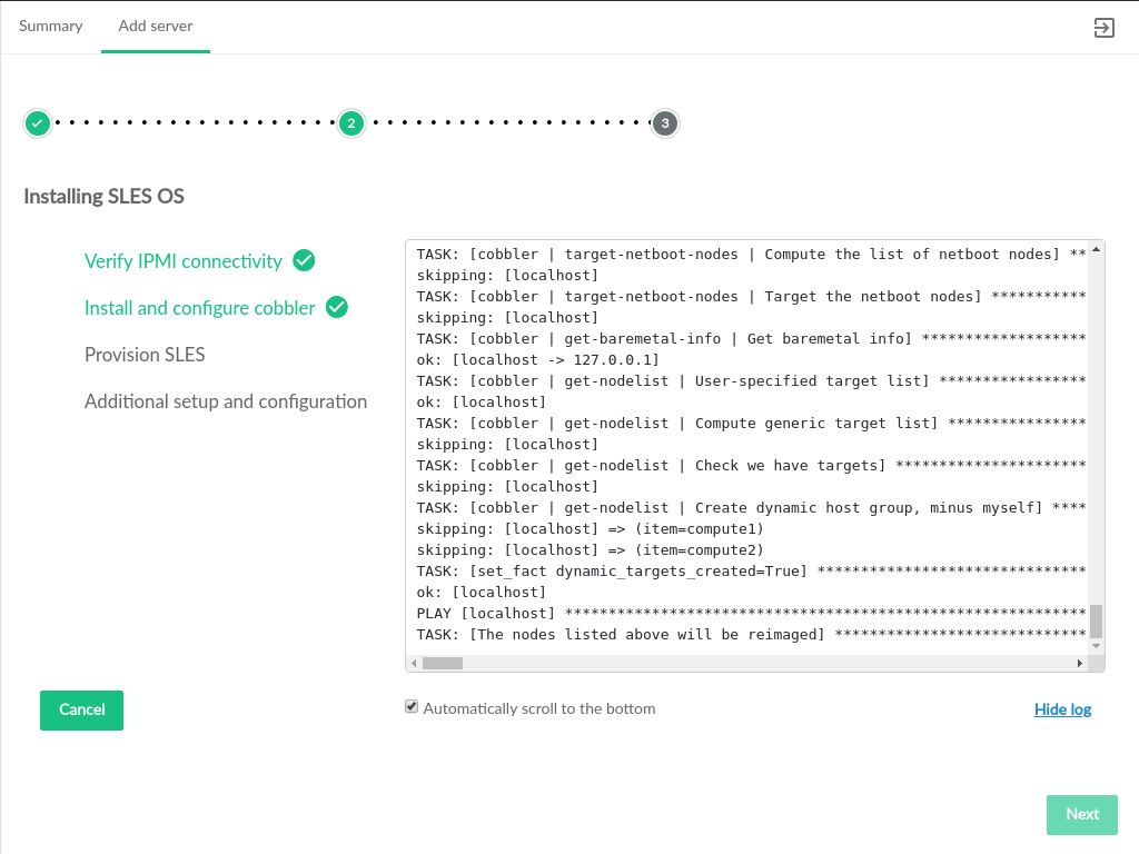
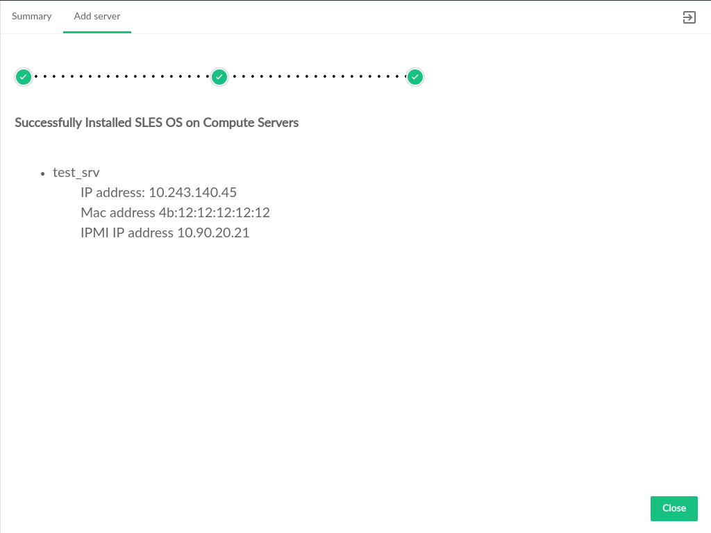
When the OS install begins, progress of the install will be displayed on screen
After OS provisioning is complete, a summary of the provisioned servers will be displayed. Clicking will return the user to the role selection page where deployment can continue.
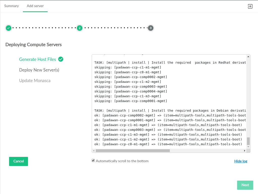
3.4.1.4 Deploy New Servers #
When all newly added servers have an OS provisioned, either via the Install OS process detailed above or having previously been provisioned outside of the Cloud Lifecycle Manager Admin UI, deployment can begin.
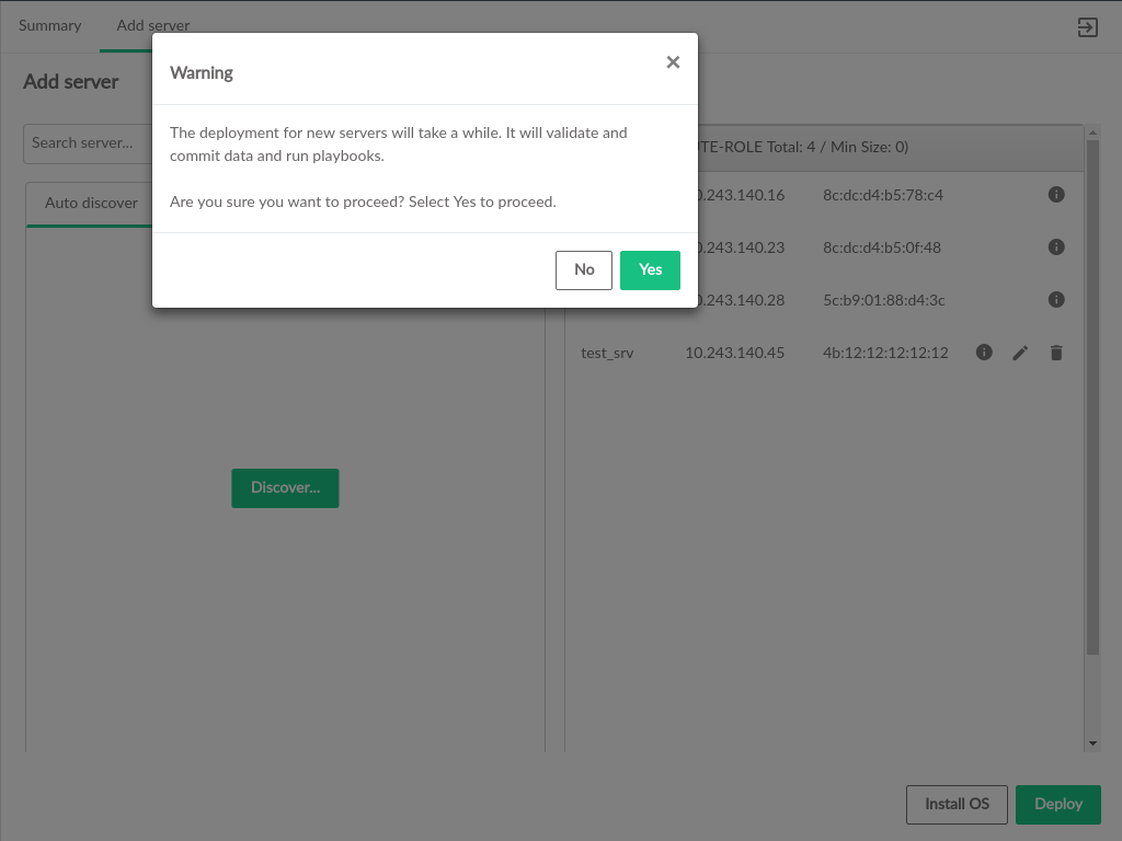
The button will be enabled when one or more new servers have been assigned roles. Clicking prompt for confirmation before beginning the deployment process
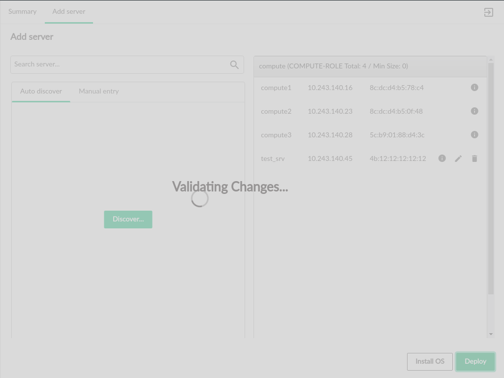
The deployment process will begin by running the Configuration Processor in basic validation mode to check the values input for the servers being added. This will check IP addresses, server groups, and NIC mappings for syntax or format errors.
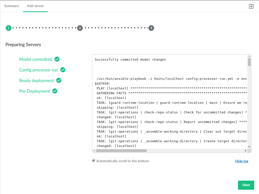
After validation is successful, the servers will be prepared for deployment. The preparation consists of running the full Configuration Processor and two additional playbooks to ready servers for deployment.
After the servers have been prepared, deployment can begin. This process
will generate a new hosts file, run the
site.yml playbook, and update monasca (if
monasca is deployed)
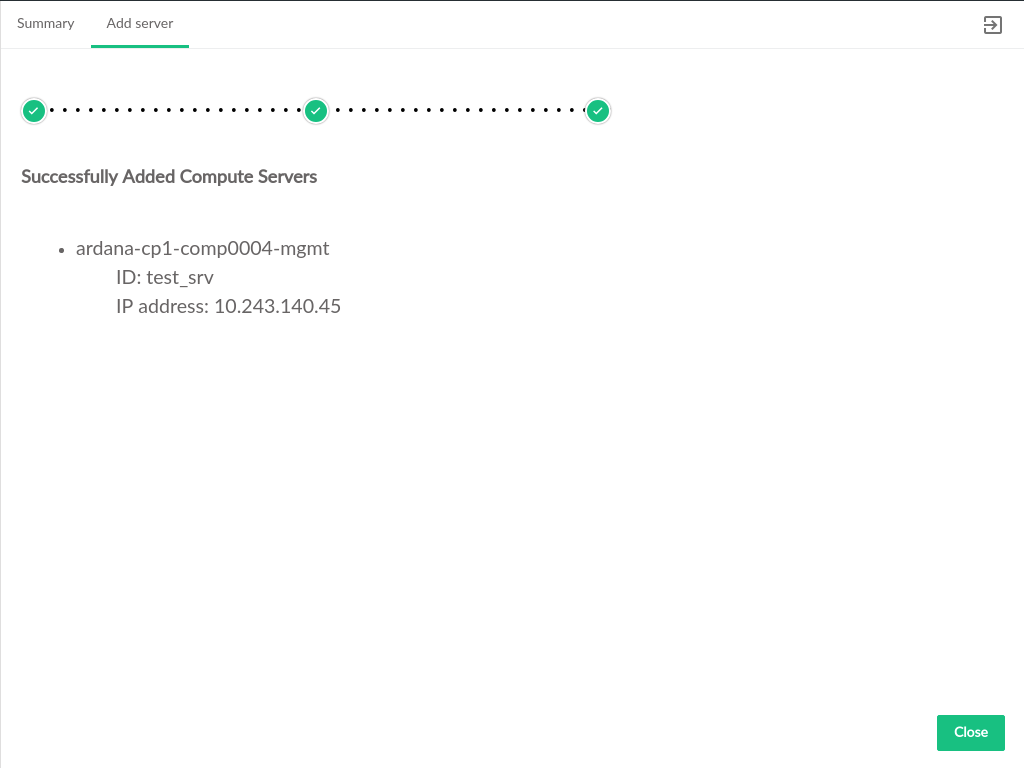
When deployment is completed, a summary page will be displayed. Clicking
will return to the Add Server page.
3.4.2 Activating Servers #
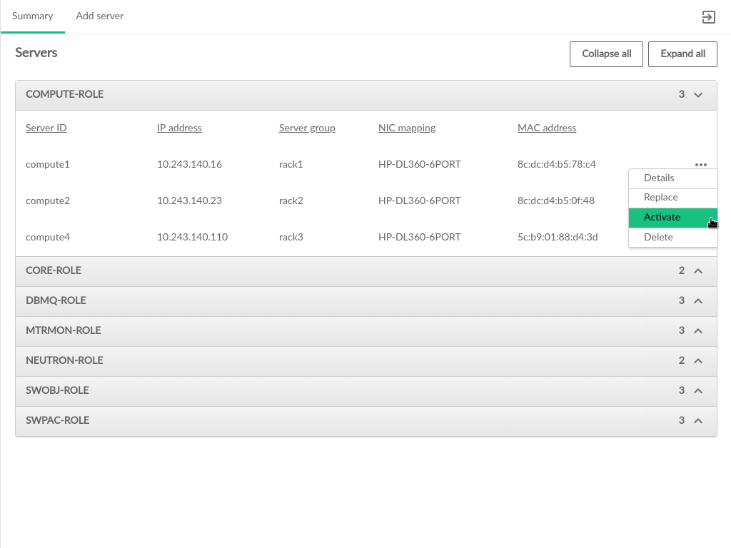
The Server Summary page in the Cloud Lifecycle Manager Admin UI allows for activating
Compute Nodes in the Cloud. Compute Nodes may be activated when
they are added to the Cloud. An activated compute node is available
for the nova-scheduler to use for hosting new VMs that are created.
Only servers that are not currently activated will have the
activation menu option available.
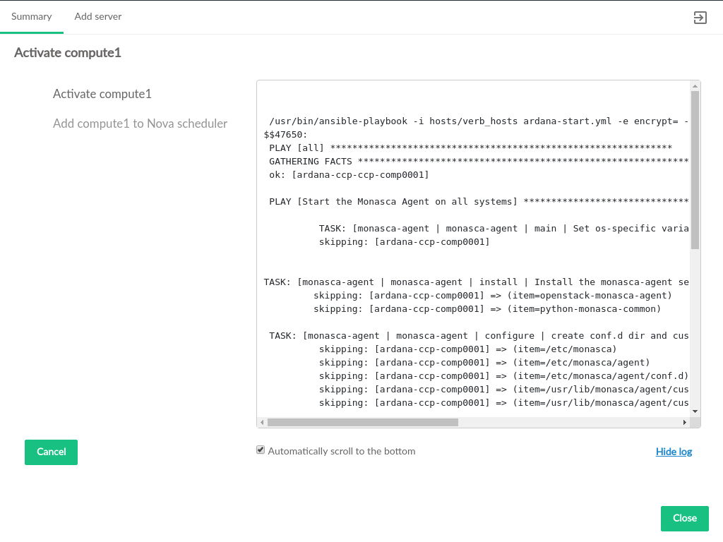
Once activation is triggered, the progress of activating the node
and adding it to the nova-scheduler is displayed.
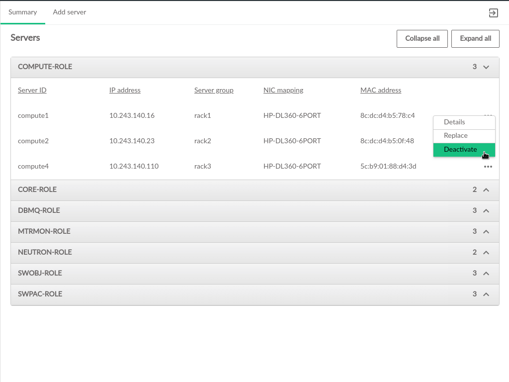
3.4.3 Deactivating Servers #
The Server Summary page in the Cloud Lifecycle Manager Admin UI allows for deactivating
Compute Nodes in the Cloud. Deactivating a Compute Node removes it from
the pool of servers that the nova-scheduler will put VMs on.
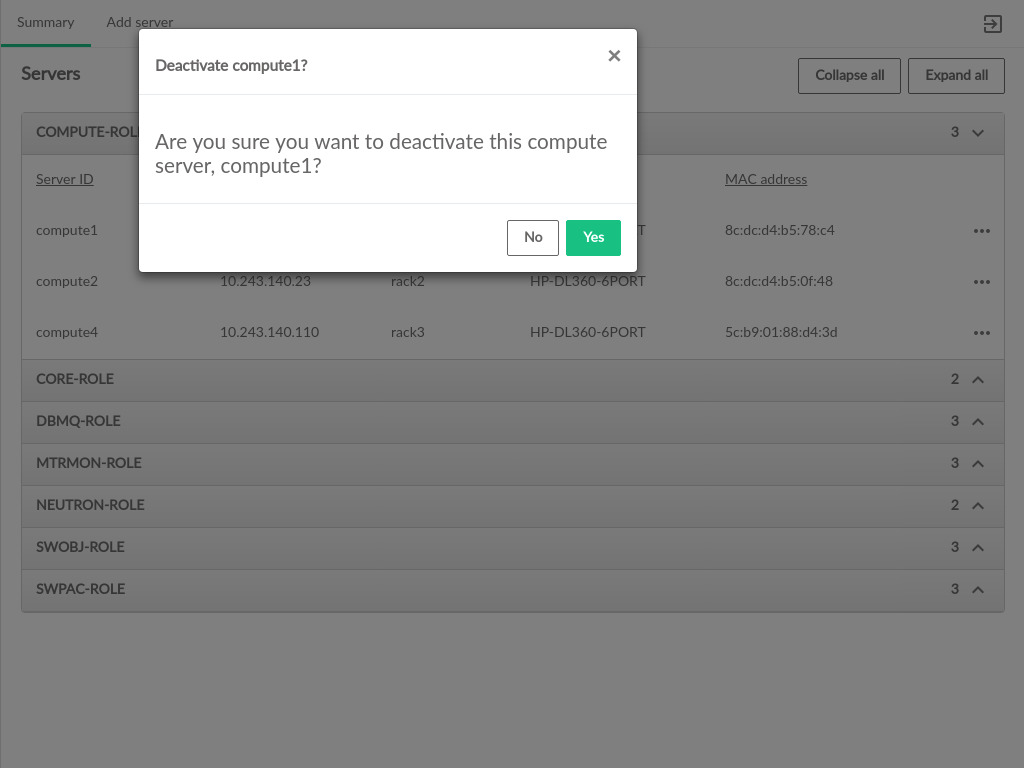
When a Compute Node is deactivated, the UI attempts to migrate any
currently running VMs from that server to an active node.
The deactivation process requires confirmation before proceeding.
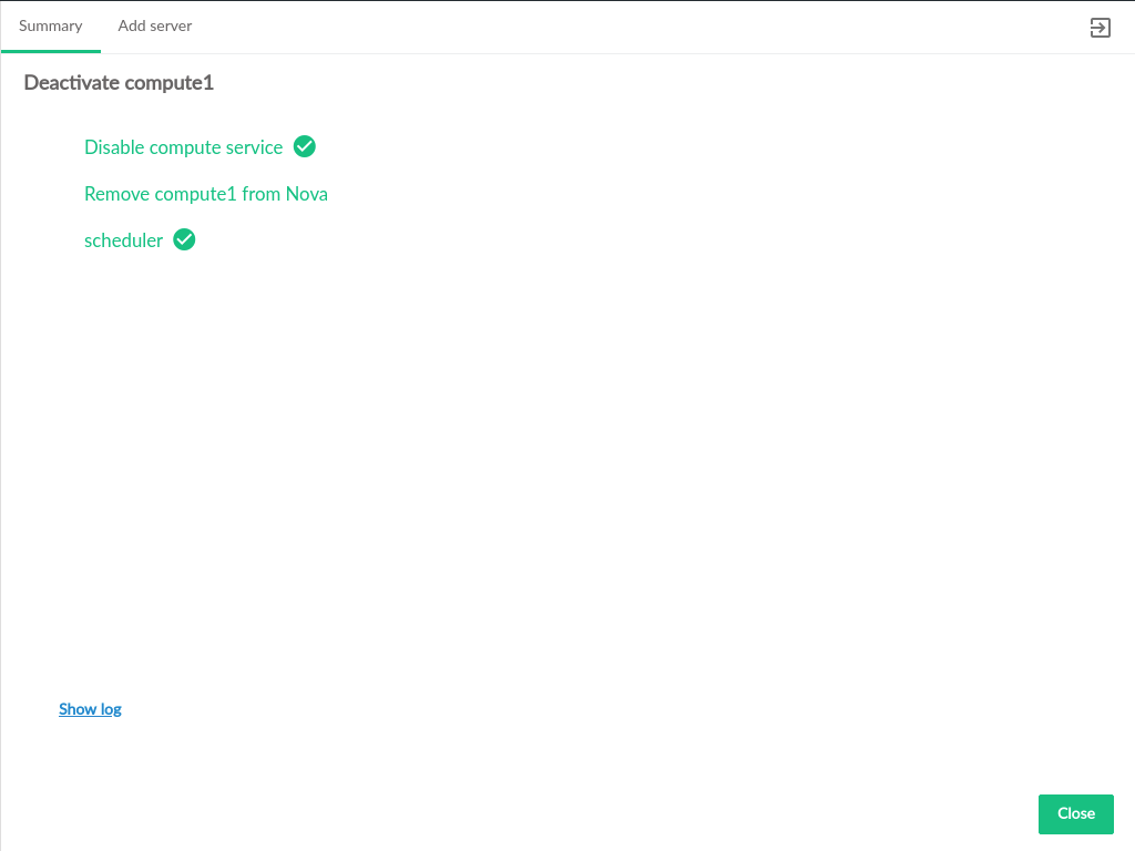
Once deactivation is triggered, the progress of deactivating the node
and removing it from the nova-scheduler is displayed.
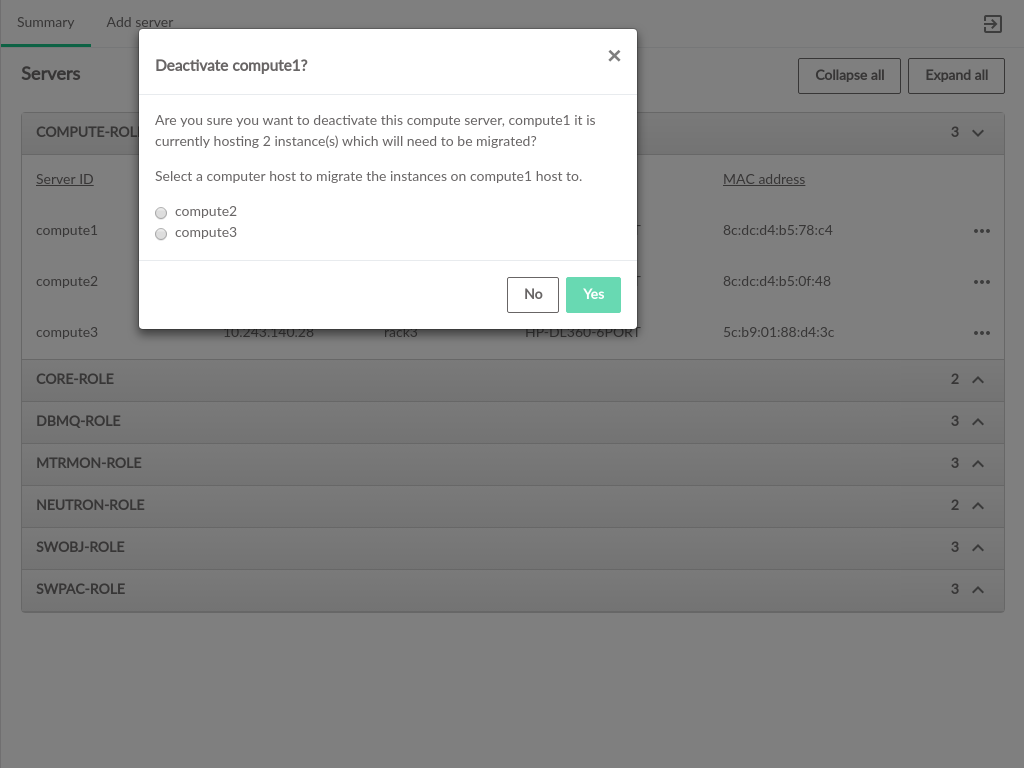
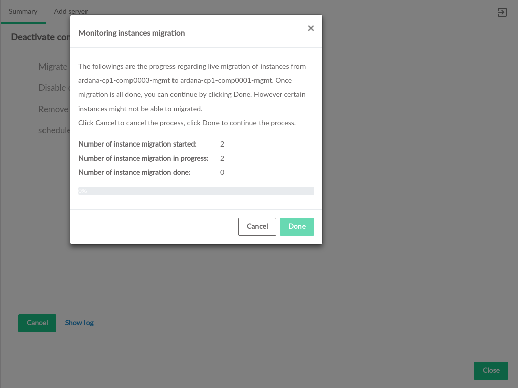
If a Compute Node selected for deactivation has VMs running on it, a prompt will appear to select where to migrate the running VMs
A summary of the VMs being migrated will be displayed, along with the progress migrating them from the deactivated Compute Node to the target host. Once the migration attempt is complete, click 'Done' to continue the deactivation process.
3.4.4 Deleting Servers #
The Server Summary page in the Cloud Lifecycle Manager Admin UI allows for deleting Compute Nodes from the Cloud. Deleting a Compute Node removes it from the cloud. Only Compute Nodes that are deactivated can be deleted.
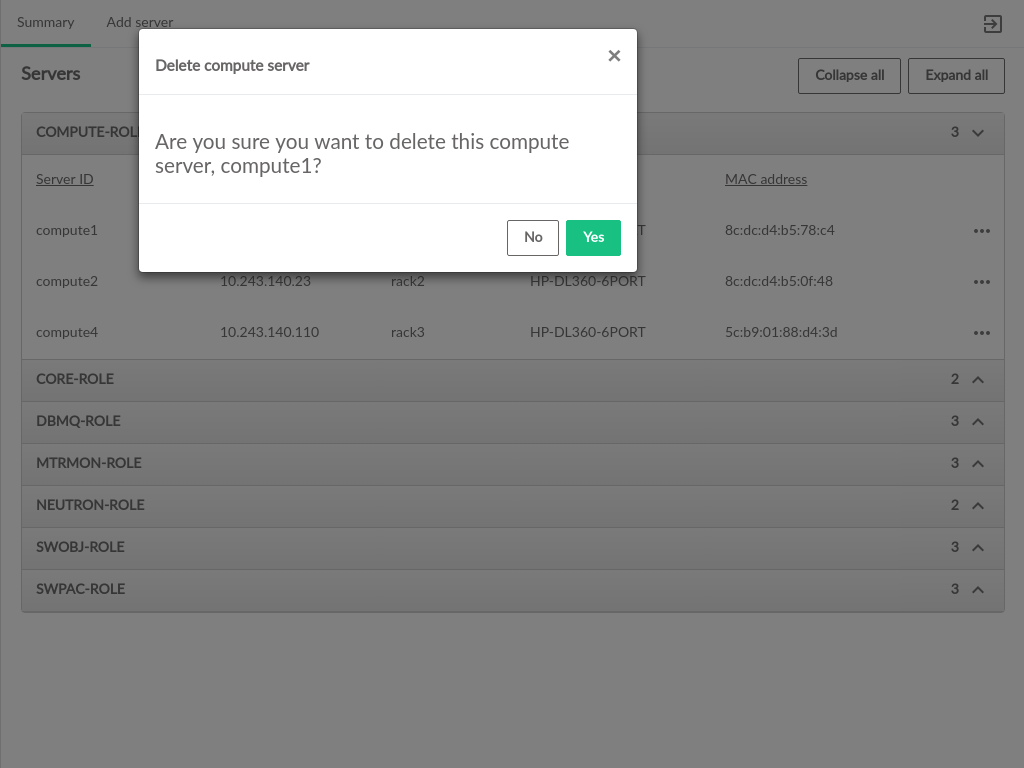
The deletion process requires confirmation before proceeding.
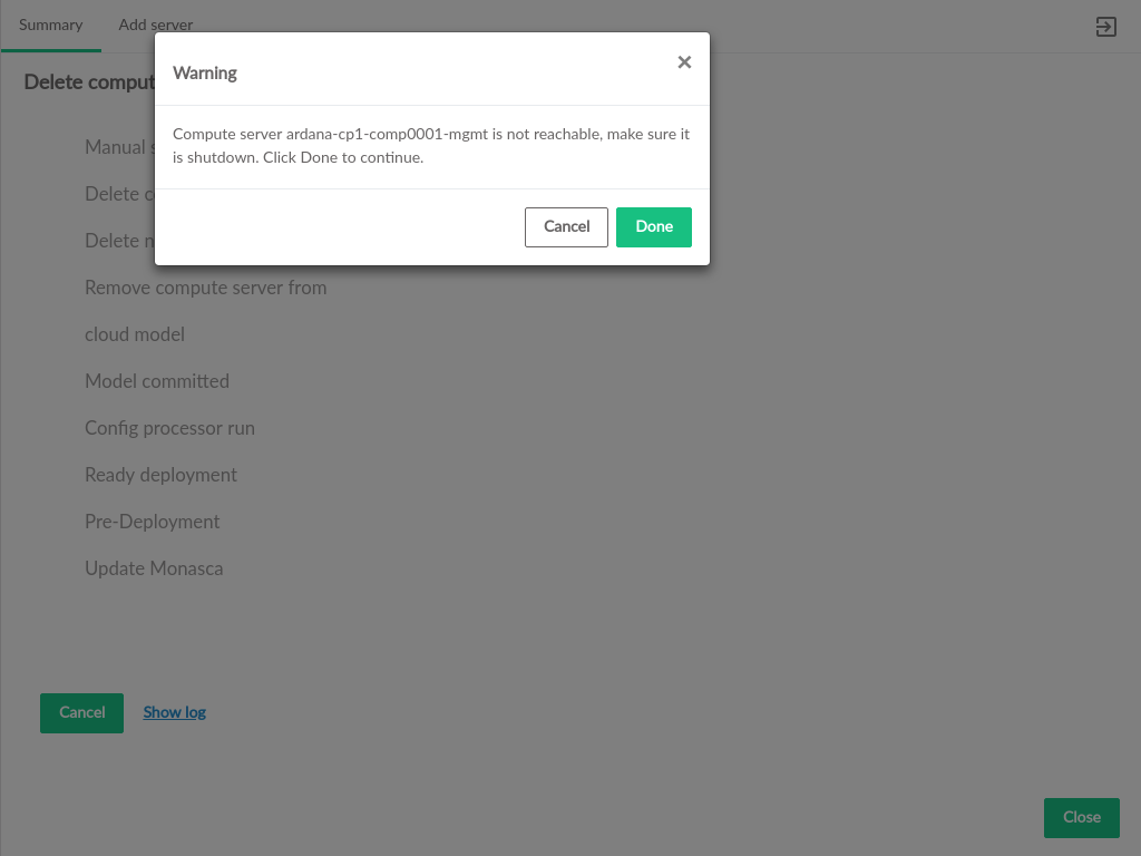
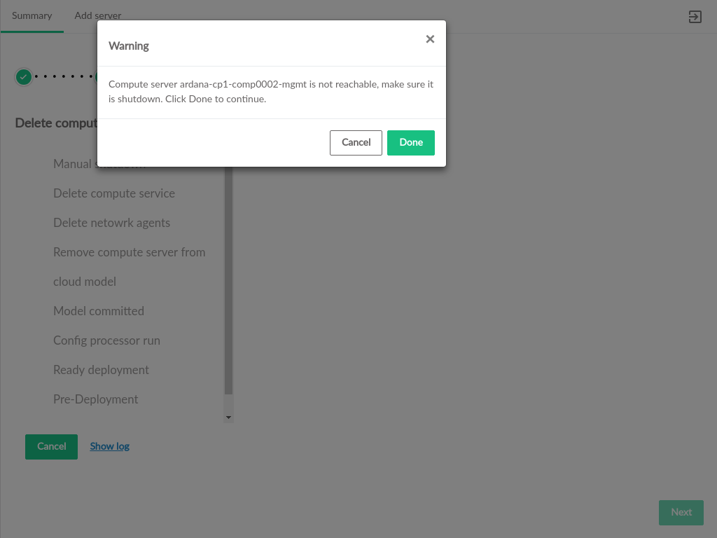
If the Compute Node is not reachable (SSH from the deployer is not possible), a warning will appear, requesting confirmation that the node is shut down or otherwise removed from the environment. Reachable Compute Nodes will be shutdown as part of the deletion process.
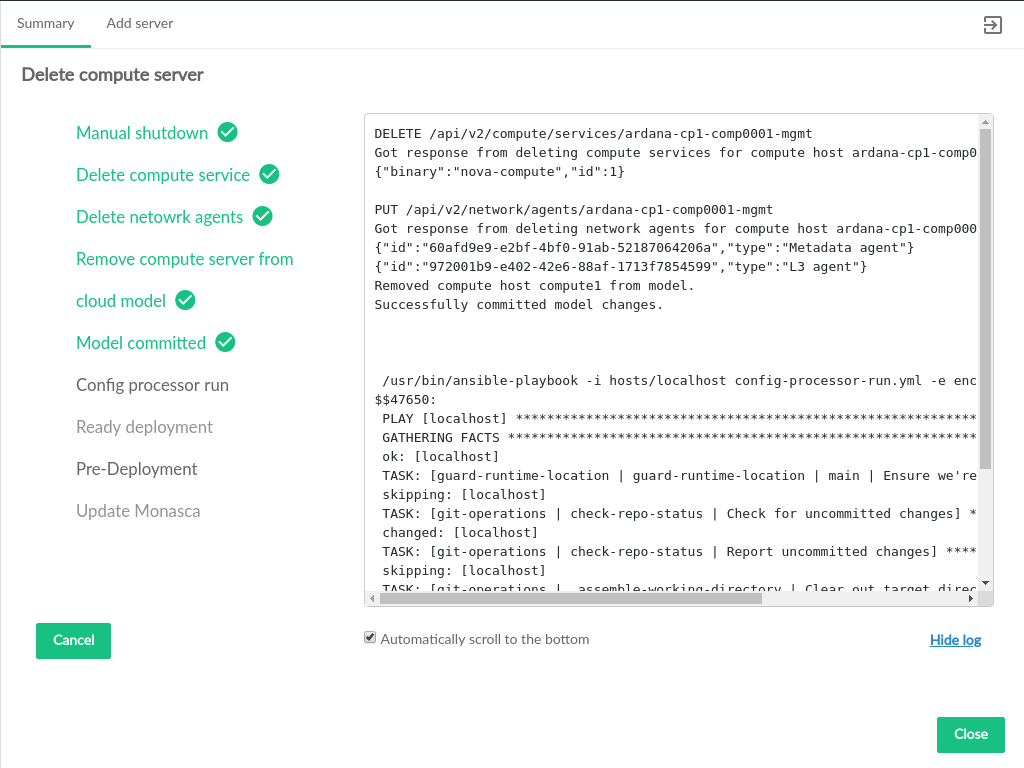
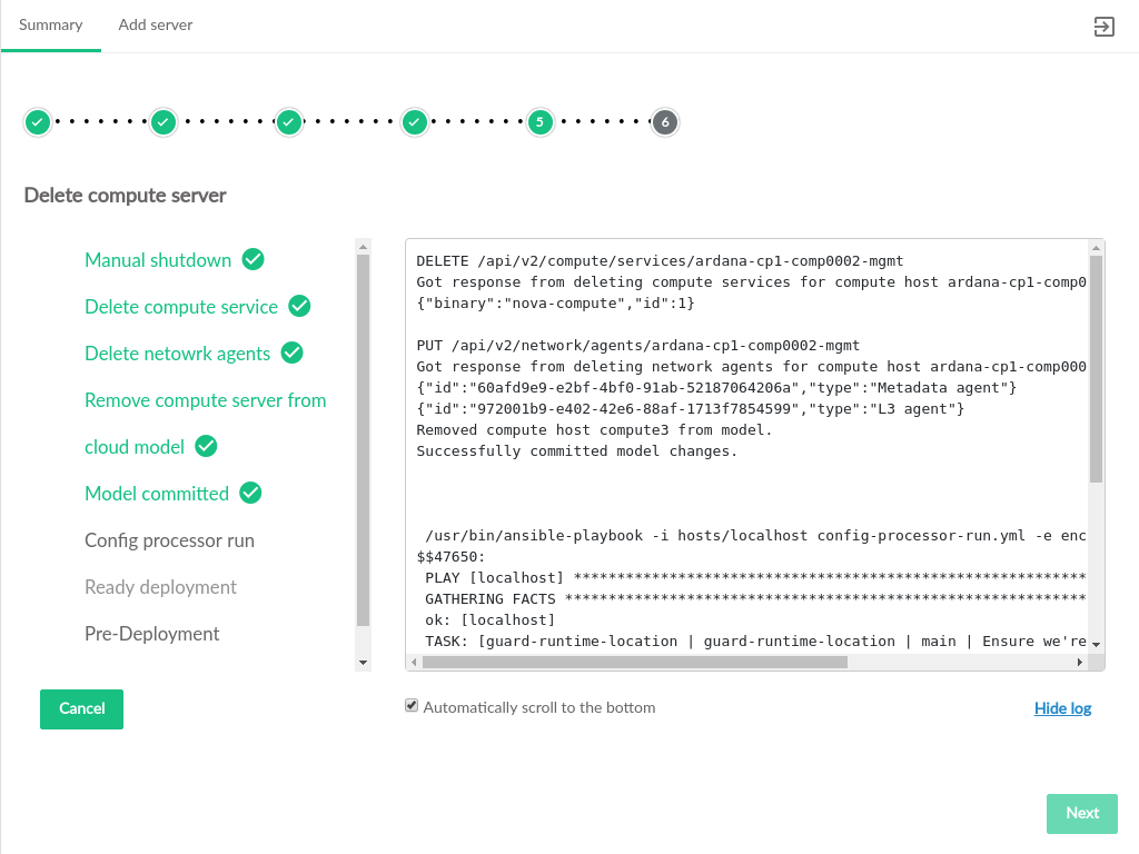
The progress of deleting the Compute Node will be displayed, including a streaming log with additional details of the running playbooks.
3.5 Server Replacement #
The process of replacing a server is initiated from the Server Summary (see Section 3.2.6, “Servers”). Replacing a server will remove the existing server from the Cloud configuration and install the new server in its place. The rest of this process varies slightly depending on the type of server being replaced.
3.5.1 Control Plane Servers #
Servers that are part of the Control Plane (generally those that are not hosting Compute VMs or ephemeral storage) are replaced "in-place". This means the replacement server has the same IP Address and is expected to have the same NIC Mapping and Server Group as the server being replaced.
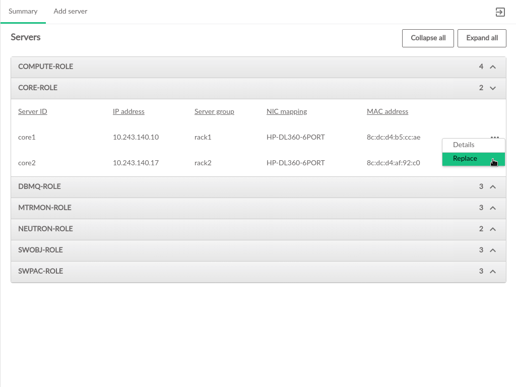
To replace a Control Plane server, click the menu to the right of the server listing on the tab of the Section 3.2.6, “Servers” page. From the menu options, select .
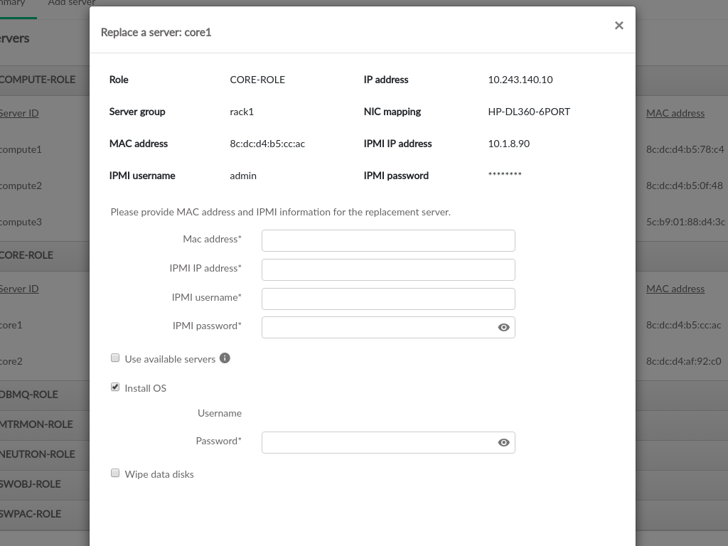
Selecting will open a dialog box that includes information about the server being replaced, as well as a form for inputting the required information for the new server.
The IPMI information for the new server is required to perform the replacement process.
- MAC Address
The hardware address of the server's primary physical ethernet adapter
- IPMI IP Address
The network address for IPMI access to the new server
- IPMI Username
The username credential for IPMI access to the new server
- IPMI Password
The password associated with the
IPMI Usernameon the new server
To use a server that has already been discovered, check the box for and select an existing server from the dropdown. This will automatically populate the server information fields above with the information previously entered/discovered for the specified server.
If SLES is not already installed, or to reinstall SLES on the new server, check the box for . The username will be pre-populated with the username from the Cloud install. Installing the OS requires specifying the password that was used for deploying the cloud so that the replacement process can access the host after the OS is installed.
The data disks on the new server will not be wiped by default, but users can specify to wipe clean the data disks as part of the replacement process.
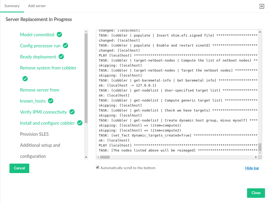
Once the new server information is set, click the button in the lower right to begin replacement. A list of the replacement process steps will be displayed, and there will be a link at the bottom of the list to show the log file as the changes are made.
When all of the steps are complete, click to return to the Servers page.
3.5.2 Compute Servers #
When servers that host VMs are replaced, the following actions happen:
a new server is added
existing instances are migrated from the existing server to the new server
the existing server is deleted from the model
The new server will not have the same IP Address and may have a different NIC Mapping and Server Group than the server being replaced.
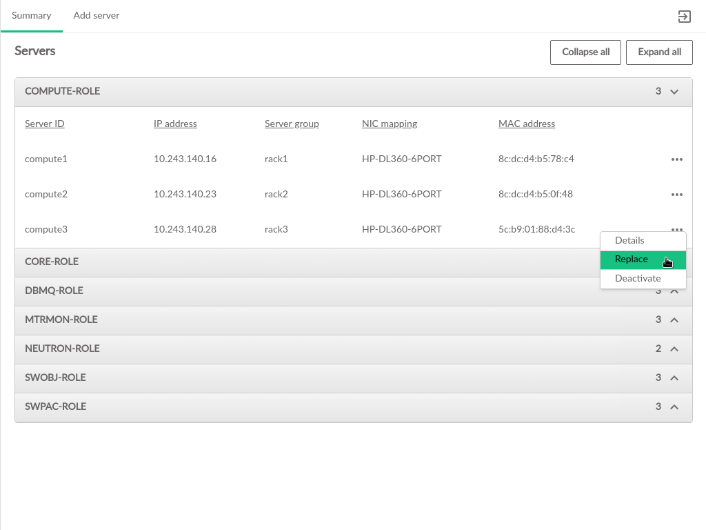
To replace a Compute server, click the menu to the right of the server listing on the tab of the Section 3.2.6, “Servers” page. From the menu options, select .
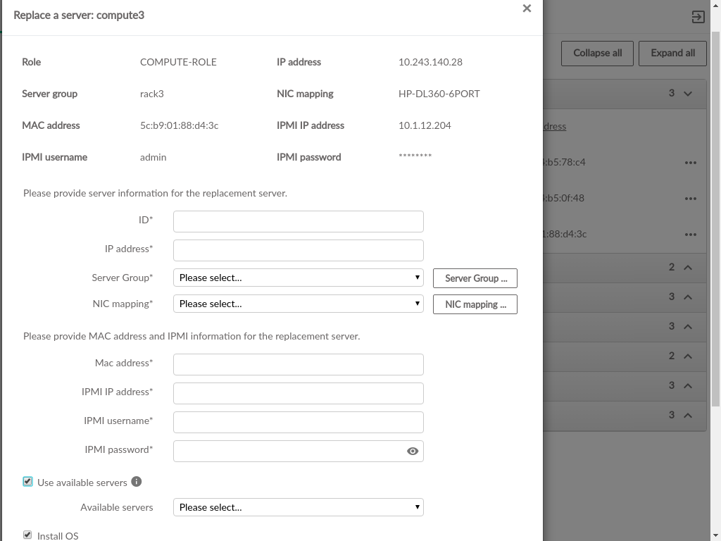
Selecting will open a dialog box that includes information about the server being replaced, and a form for inputting the required information for the new server.
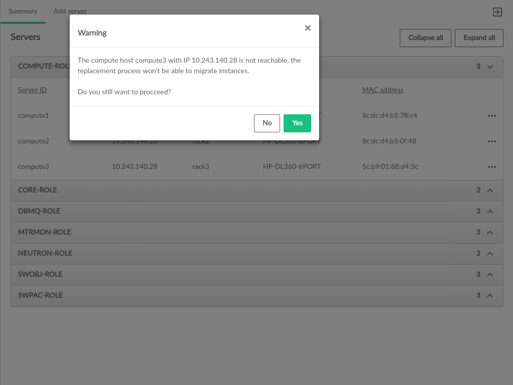
If the IP address of the server being replaced cannot be reached by the deployer, a warning will appear to verify that the replacement should continue.
Replacing a Compute server involves adding the new server and then performing migration. This requires some new information:
an unused IP address
a new ID
selections for Server Group and NIC Mapping, which do not need to match the original server.
- ID
This is the ID of the server in the data model. This does not necessarily correspond to any DNS or other naming labels of a host, unless the host ID was set that way during install.
- IP Address
The management network IP address of the server
- Server Group
The server group which this server is assigned to. If the required Server Group does not exist, it can be created
- NIC Mapping
The NIC mapping that describes the PCI slot addresses for the server's ethernet adapters. If the required NIC mapping does not exist, it can be created
The IPMI information for the new server is also required to perform the replacement process.
- Mac Address
The hardware address of the server's primary physical ethernet adapter
- IPMI IP Address
The network address for IPMI access to the new server
- IPMI Username
The username credential for IPMI access to the new server
- IPMI Password
The password associated with the
IPMI Username
To use a server that has already been discovered, check the box for and select an existing server from the dropdown. This will automatically populate the server information fields above with the information previously entered/discovered for the specified server.
If SLES is not already installed, or to reinstall SLES on the new server, check the box for . The username will be pre-populated with the username from the Cloud install. Installing the OS requires specifying the password that was used for deploying the cloud so that the replacement process can access the host after the OS is installed.
The data disks on the new server will not be wiped by default, but
wipe clean can specified for the data disks as
part of the replacement process.
When the new server information is set, click the button in the lower right to begin replacement. The configuration processor will be run to validate that the entered information is compatible with the configuration of the Cloud.
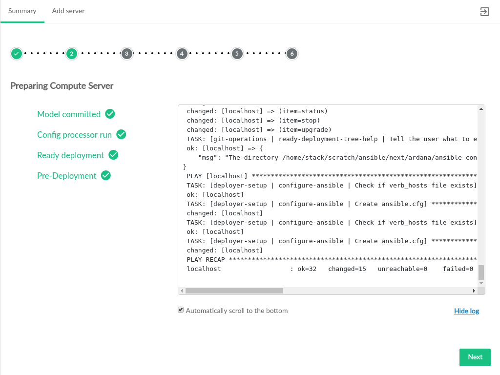
When validation has completed, the Compute replacement takes place in several distinct steps, and each will have its own page with a list of process steps displayed. A link at the bottom of the list can show the log file as the changes are made.
Install SLES if that option was selected
Figure 3.54: Install SLES on New Compute #Commit the changes to the data model and run the configuration processor
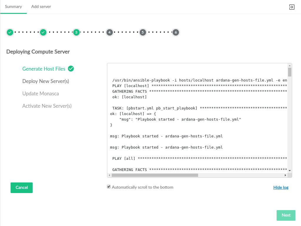
Figure 3.55: Prepare Compute Server #Deploy the new server, install services on it, update monasca (if installed), activate the server with nova so that it can host VMs.
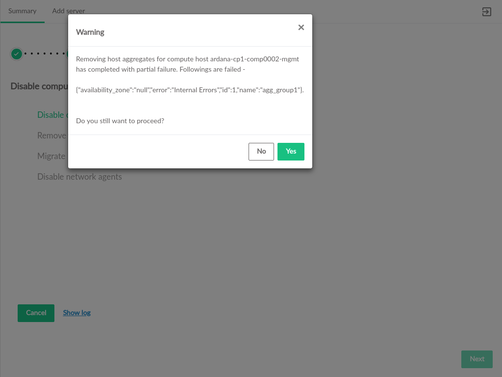
Figure 3.56: Deploy New Compute Server #Disable the existing server. If the existing server is unreachable, there may be warnings about disabling services on that server.
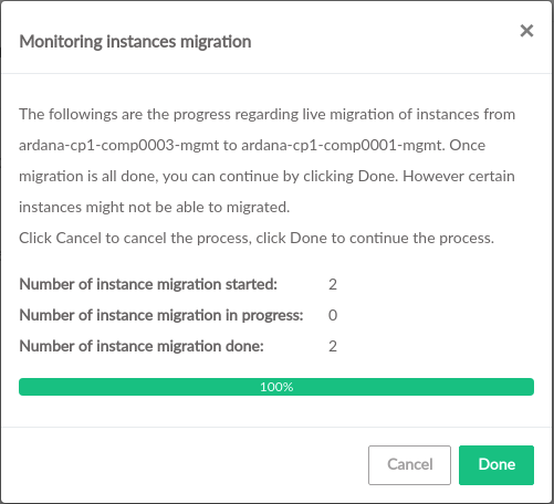
Figure 3.57: Host Aggregate Removal Warning #If the existing server is reachable, instances on that server will be migrated to the new server.
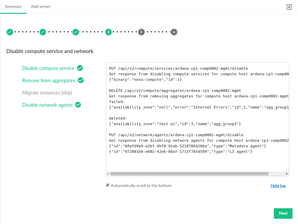
Figure 3.58: Migrate Instances from Existing Compute Server #If the existing server is not reachable, the migration step will be skipped.
Figure 3.59: Disable Existing Compute Server #Remove the existing server from the model and update the cloud configuration. If the server is not reachable, the user is asked to verify that the server is shut down. If server is reachable, the cloud services running on it will be stopped and the server will be shut down as part of the removal from the Cloud.
Figure 3.60: Existing Server Shutdown Check #Upon verification that the unreachable host is shut down, it will be removed from the data model.
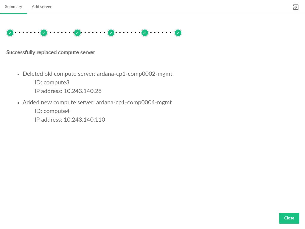
Figure 3.61: Existing Server Delete #After the model has been updated, a summary of the changes will appear. Click to return to the server summary screen.
Figure 3.62: Compute Replacement Summary #

