Virtual Private Cloud
|
All features that use Kube-OVN are considered experimental. For more information about experimental features, see Feature Labels. |
A virtual private cloud (VPC) is a logically isolated network that provides full control over IP addresses, subnets, route tables, firewalls, and gateways within a cloud infrastructure. VPCs allow the secure and scalable deployment of virtualized resources such as compute, storage, and container services.
The following table outlines the key components of a VPC:
| Component | Description |
|---|---|
VPC |
Top-level network space with a user-defined IP CIDR range |
subnet |
Subdivision of the VPC IP space; can be public or private |
route table |
Defines traffic routing rules within and outside the VPC |
internet gateway |
Enables outbound internet access for public subnets |
NAT gateway |
Allows private subnets to access the internet (outbound only) |
security group |
Virtual firewall that controls inbound and outbound traffic per instance |
VPC peering |
Optional peering or hybrid connections between different VPCs or on-premises networks |
SUSE Virtualization and Kube-OVN integration architecture
The following diagram illustrates how VPCs, subnets, overlay networks, and virtual machines are logically connected in SUSE Virtualization with Kube-OVN. This architecture includes public and private subnets, allowing separation of internet-facing traffic from internal resources. Moreover, this architecture enables scalable, isolated L3 and L2 network structures across the cluster.

| Component | Platform | Logical Responsibility |
|---|---|---|
Kube-OVN |
Top-level L3 domain, manages subnet groupings |
|
Kube-OVN |
CIDR assignment, routing, gateway, firewall rules |
|
SUSE Virtualization |
L2 virtual switch (OVS bridge), mapped to subnet |
|
SUSE Virtualization |
Runs compute workloads, connected to overlay network |
This architecture has the following key characteristics:
-
Kube-OVN creates the VPC and its subnets.
Each subnet includes a CIDR and gateway IP, and binds to an overlay network (as provider). Kube-OVN enforces a one-to-one mapping between the subnet and the overlay network to avoid ambiguous routing, traffic collisions, and isolation issues.
-
SUSE Virtualization defines the overlay networks.
Each overlay network is considered a provider in Kube-OVN. When you create a subnet on the SUSE Virtualization UI, you can select these overlay networks in the Provider list (type:
OverlayNetwork) on the Subnet:Create screen. -
SUSE Virtualization provisions virtual machines that are connected to an overlay network.
Each virtual machine uses the Kube-OVN IPAM to request an IP address after booting. The virtual machine receives its IP address, gateway, and routing information from the associated subnet.
-
Kube-OVN handles all L3 logic (routing, NAT, VPC peering, and isolation).
SUSE Virtualization focuses purely on compute and network attachment. Network policy enforcement, private subnets, and NAT egress are managed by Kube-OVN.
This architecture offers the following benefits:
-
Clear separation of concerns: SUSE Virtualization handles virtualization; Kube-OVN handles SDN
-
Scalability: New VPCs, subnets, and peering don’t require changes in SUSE Virtualization core
-
Kubernetes-native networking: Kube-OVN integrates tightly with Kubernetes, supporting CRDs, policies, etc.
-
Isolation and observability: Centralized control over IPs, ACLs, and routing through Kube-OVN
VPC and subnet configuration
VPC settings
In SUSE Virtualization, a virtual private cloud (VPC) is a logical network container that helps manage and isolate subnets and traffic. It defines routing, NAT, and network segmentation.
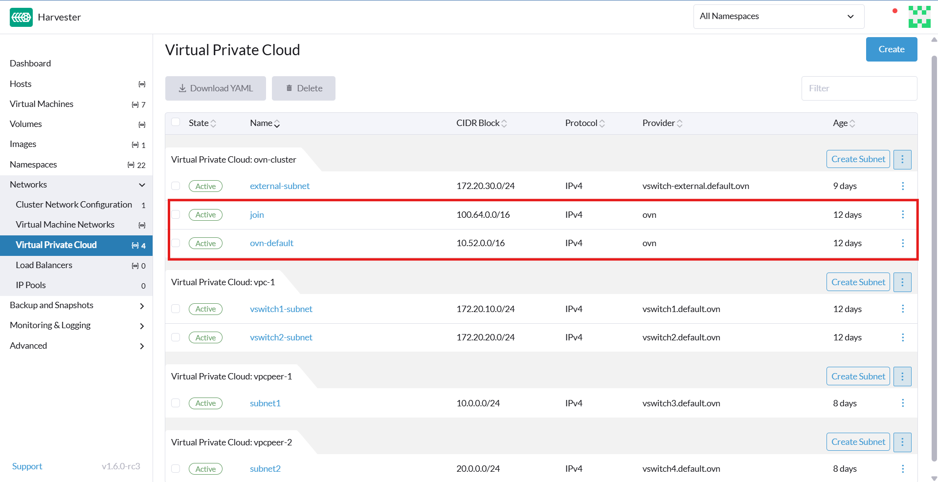
SUSE Virtualization provides a default VPC named ovn-cluster, and two associated subnets named ovn-default and join for internal Kube-OVN operations. You can create additional VPCs by clicking Create on the Virtual Private Cloud screen.
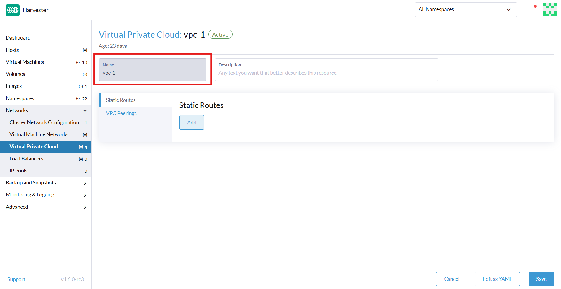
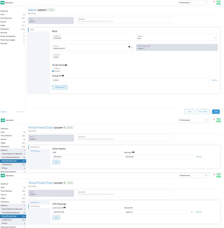
When creating custom VPCs, you must configure settings related to the routes defined for directing traffic and connections that enable communication between the local and remote VPCs. The following table outlines the settings on the Virtual Private Cloud details screen:
| Section | Setting | Description |
|---|---|---|
General information |
Name |
Name of the VPC |
General information |
Description |
Description of the VPC |
Static Routes tab |
CIDR |
Destination IP address range for the route (for example, |
Static Routes tab |
Next Hop IP |
IP address to which traffic for the CIDR should be forwarded (for example, the gateway or router IP address) |
VPC Peerings tab |
Local Connect IP |
IP address on the local VPC to be used for the peering connection |
VPC Peerings tab |
Remote VPC |
Target remote VPC that is peered with the local VPC |
Subnet settings
Each subnet defines a CIDR block and gateway, and is mapped to a SUSE Virtualization overlay network (virtual switch). It also includes controls for NAT and access rules.
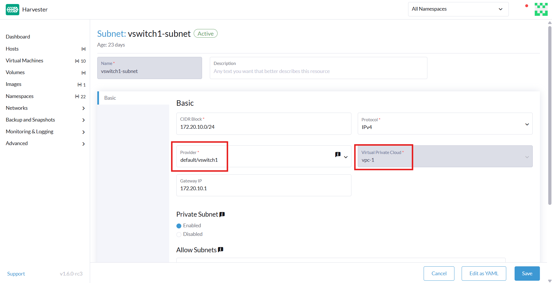
When creating subnets, you must configure settings that are relevant to your use case. In most cases, you can get started by just configuring the CIDR Block, Gateway, and Provider. The following table outlines the settings on the Subnet details screen:
| Section | Setting | Description |
|---|---|---|
General information |
Name |
Name of the subnet |
General information |
Description |
Description of the subnet |
Basic |
CIDR Block |
IP address range assigned to the subnet (for example, |
Basic tab |
Protocol |
Network protocol version used for this subnet (IPv4 or IPv6) |
Basic tab |
Provider |
Overlay network (virtual switch) to which the subnet is bound |
Basic tab |
Virtual Private Cloud |
Virtual private cloud that the subnet belongs to |
Basic tab |
Gateway |
IP address that acts as the default gateway for virtual machines in the subnet |
Basic tab |
Private Subnet |
Setting that restricts access to the subnet and ensures network isolation |
Basic tab |
Allow Subnets |
CIDRs that are allowed to access the subnet when Private Subnet is enabled |
Basic tab |
Exclude IPs |
List of IP addresses that should not be automatically assigned to virtual machines |
Each created subnet has a setting called <<`natOutgoing` setting,natOutgoing>>, which enables network address translation (NAT) for traffic leaving the subnet and going to destinations outside the VPC. This setting is disabled by default. To enable it, you must edit the subnet’s YAML configuration and set the value to natOutgoing: true.
By default, subnets in different VPCs are unable to communicate directly. To enable secure and controlled communication between them, you must establish a VPC peering connection. Without it, subnet traffic in each VPC remains completely isolated.
|
VPC peering connections can only be established between custom VPCs. |
Creating a VPC
Perform the following steps to create and configure a VPC.
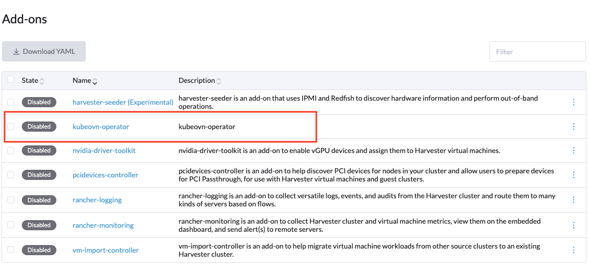
-
Enable kubeovn-operator.
The kubeovn-operator add-on deploys Kube-OVN to the SUSE Virtualization cluster.
-
You must create a separate overlay network for each subnet that you plan to create.
-
Create a VPC.
-
Go to Networks → Virtual Private Cloud, and then click Create.
-
On the Virtual Private Cloud:Create screen, specify a unique name for the VPC.
-
Click Create.
-
-
Create subnets.
-
Go to Networks → Virtual Private Cloud.
-
Locate the VPC you created, and then click Create Subnet.
-
On the Subnet:Create screen, configure the settings that are relevant to your environment.
You must link each subnet to a dedicated overlay network. In the Provider field, the SUSE Virtualization UI only shows overlay networks that are not linked to other subnets, automatically enforcing the one-to-one mapping.
-
Click Edit as YAML.
-
Under
spec, addenableDHCP: true.This ensures that virtual machines connected to the subnet can obtain the correct default route options.
-
(Optional) Use the
dhcpV4Optionsfield to specify additional DHCP settings such as the DNS server passed to the virtual machine workloads.Example:
        spec:
            cidrBlock: 172.20.0.0/16
            default: false
            dhcpV4Options: dns_server=8.8.8.8
            enableDHCP: true
            enableLb: true
            excludeIps:
                - 172.20.0.1
            #    - string
            gateway: 172.20.0.1
            gatewayNode: ''
            gatewayType: distributed
            natOutgoing: true
            private: false
            protocol: IPv4
            provider: ovn-subnet-1.default.ovn
            vpc: ovn-cluster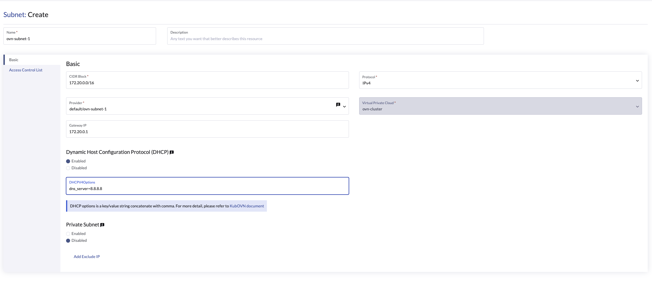
-
Click Create.
-
-
Create virtual machines.
-
Configure the settings that are relevant to each virtual machine.
On the Networks tab, you must select the correct overlay network in the Network field.
-
Click Create.
The virtual machine obtains its IP address from the subnet that it is connected to.
-
Select ⋮ → Edit YAML.
-
Change the value of
spec.domain.devices.interface.binding.nametomanagedtap.This ensures that the virtual machine obtains the correct DHCP options from the subnet instead of using the default DHCP server from KubeVirt.
If you do not perform this step, the virtual machine will not have a default route. Until the default route is properly configured on the guest operating system, attempts to access external destinations and virtual machines on different subnets will fail.
For more information, see Overlay network limitations.
-
Restart each virtual machine.
-
Sample VPC configuration and verification
-
Create overlay networks with the following settings:
-
Name:
vswitch1andvswitch2 -
Type:
OverlayNetwork
-
-
Create a VPC named
vpc-1. -
Create two subnets in
vpc-1with the following settings:Name CIDR Provider Gateway IP vswitch1-subnet172.20.10.0/24default/vswitch1172.20.10.1vswitch2-subnet172.20.20.0/24default/vswitch2172.20.20.1 -
Create three virtual machines with the following settings:
-
Name:
vm1-vswitch1,vm2-vswitch1, andvm1-vswitch2 -
Basics tab
-
CPU:
1 -
Memory:
2
-
-
Volumes tab
-
Image Volume: A cloud image (for example,
noble-server-cloudimg-amd64)
-
-
Networks tab
-
Network:
default/vswitch1
-
-
Advanced Options tab
users:
    - name: ubuntu
      groups: [ sudo ]
      shell: /bin/bash
      sudo: ALL=(ALL) NOPASSWD:ALL
      lock\_passwd: false
Once the virtual machines start running, the node displays the NTP server
0.suse.pool.ntp.organd the IP address.
-
-
Open the serial consoles of
vm1-vswitch1andvm1-vswitch2, and then add a default route on each (if none exists) using the following commands:-
vm1-vswitch1(172.20.10.6):#sudo ip route add default via 172.20.10.1 dev enp1s0
-
vm1-vswitch2(172.20.20.3):#sudo ip route add default via 172.20.20.1 dev enp1s0
If a virtual machine wants to send traffic to an unknown network (not in the local subnet), the traffic must be forwarded to the specified gateway IP configured for the connected subnet using the specified network interface. In this example,
vm1-vswitch1must forward traffic via172.20.10.1, whilevm1-vswitch2must forward traffic via172.20.20.1. Both virtual machines use the network interfaceenp1s0.
-
-
Verify connectivity using the
pingcommand.-
Use
vm1-vswitch1(172.20.10.6) to pingvm1-vswitch2(172.20.20.3). -
Use
vm1-vswitch2(172.20.20.3) to pingvm1-vswitch1(172.20.10.6).Since
vm1-vswitch1andvm1-vswitch2are on the same subnet, they can communicate with each other without any default route settings.If no default route exists on the virtual machine before you run the ping command, the console displays the message
ping: connect: Network is unreachable.
-
Private subnet setting
When the Private Subnet setting is enabled on a subnet, it cannot communicate with other subnets in the same VPC by default. Cross-subnet traffic is allowed only if you add the other subnets' CIDR blocks to the private subnet’s Allow Subnets list.
The Private Subnet setting offers the following benefits:
-
Fine-grained network segmentation (micro-segmentation)
-
Stronger network isolation within the VPC and reduced potential attack surface
-
Prevention of unauthorized access to sensitive or critical resources inside the VPC
-
Controlled, selective cross-subnet communication via the Allow Subnets list
Sample private subnet verification
-
Go to Networks → Virtual Private Cloud.
-
Locate
vswitch1-subnet, and then select ⋮ → Edit Config. -
Enable the Private Subnet setting.
-
Open the serial console of
vm1-vswitch1(172.20.10.6), and then pingvm1-vswitch2(172.20.20.3).The ping attempt fails because
vm1-vswitch1is isolated. Enabling the Private Subnet setting onvswitch1-subnetprohibitsvm1-vswitch1from communicating with virtual machines in other subnets. -
Return to the Virtual Private Cloud screen, locate
vswitch1-subnet, and then select ⋮ → Edit Config. -
Add
172.20.20.0/24to the Allow Subnets field. -
Open the serial console of
vm1-vswitch1(172.20.10.6), and then pingvm1-vswitch2(172.20.20.3).The ping attempt is successful.
natOutgoing setting
The natOutgoing setting enables network address translation (NAT) for traffic leaving the subnet and going to destinations outside the VPC. This setting is disabled by default. To enable it, you must edit the subnet’s YAML configuration and set the value to natOutgoing: true.
Sample natOutgoing configuration and verification
-
Create an overlay network with the following settings:
-
Name:
vswitch-external -
Type:
OverlayNetwork
-
-
In the
ovn-clusterVPC, create a subnet with the following settings:-
Name:
external-subnet -
CIDR Block:
172.20.30.0/24 -
Provider:
default/vswitch-external -
Gateway IP:
172.20.30.1
-
-
Create a virtual machine with the following settings:
-
Name:
vm-external -
Basics tab
-
CPU:
1 -
Memory:
2
-
-
Volumes tab
-
Image Volume: A cloud image (for example,
noble-server-cloudimg-amd64)
-
-
Networks tab
-
Network:
default/vswitch-external
-
-
Advanced Options tab
users:
    - name: ubuntu
      groups: [ sudo ]
      shell: /bin/bash
      sudo: ALL=(ALL) NOPASSWD:ALL
      lock\_passwd: false
-
-
Open the serial console of
vm-external(172.20.30.2), and then ping8.8.8.8.The console displays the message
ping: connect: Network is unreachable. -
Add a default route using the following command:
#sudo ip route add default via 172.20.30.1 dev enp1s0
Again, the ping attempt fails.
-
Go to the Virtual Private Cloud screen.
-
Locate
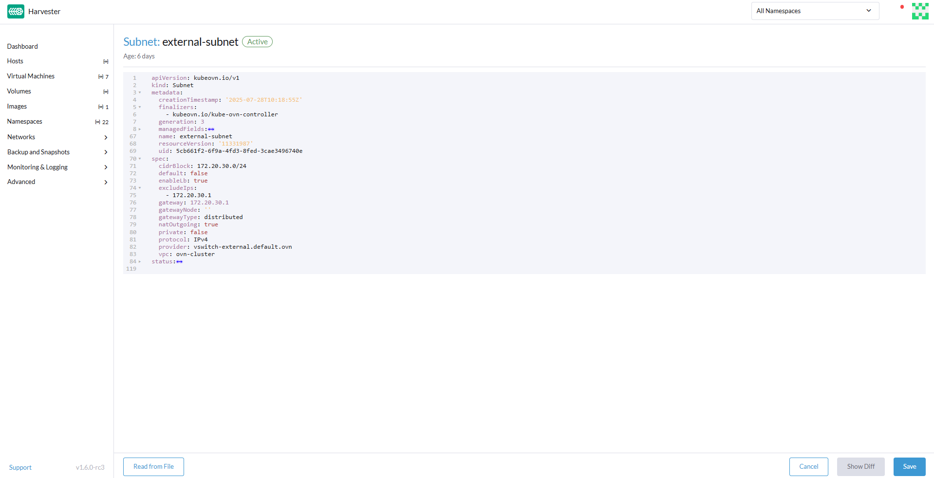
external-subnet, and then select ⋮ → Edit Config. -
Click Edit as YAML.
-
Locate the
natOutgoingfield, and then change the value totrue. -
Click Save.
-
Open the serial console of
vm-external(172.20.30.2), and then ping8.8.8.8.The ping attempt is successful.
VPC peering
VPC peering is a networking connection that enables virtual machines in different VPCs to communicate using private IP addresses.
Each VPC is a separate network namespace with its own CIDR block, routing table, and isolation boundary. Without VPC peering, virtual machines are isolated even when they are hosted within the same SUSE Virtualization cluster. Once a peering connection is established, routing rules are automatically updated to allow virtual machines to communicate privately.
VPC peering offers the following benefits:
-
The VPCs remain logically and administratively isolated. This is ideal for multi-tenant setups that require strong network isolation with optional connectivity. You can organize workloads by team, function, or environment (for example, development vs. production).
-
Traffic between VPCs does not traverse the public internet, reducing exposure. You can also use route tables and firewall rules to tightly control network access.
-
Keeping traffic within the internal cloud network not only improves performance but also lowers costs, providing a significant advantage over using the public internet or VPNs.
The following diagram shows how VPCs and subnets in Kube-OVN map to overlay networks and virtual machines in SUSE Virtualization. This architecture enables you to create scalable and isolated L3 and L2 network structures across the cluster.

VPC peering configuration examples
-
Example 1: Successful cross-VPC communication
VPC Name VPC CIDR Subnet Static Route vpcpeer-110.0.0.0/1610.0.0.0/2420.0.0.0/16 → 169.254.0.2vpcpeer-220.0.0.0/1620.0.0.0/2410.0.0.0/16 → 169.254.0.1Since both subnets fall within their respective VPC CIDRs, the routing works correctly and cross-VPC communication is successful.
-
Example 2: Unsuccessful cross-VPC communication due to routing configuration issue
VPC Name VPC CIDR Subnet Static Route vpcpeer-110.0.0.0/1610.1.0.0/2420.0.0.0/16 → 169.254.0.2vpcpeer-220.0.0.0/1620.1.0.0/2410.0.0.0/16 → 169.254.0.1The target subnet IP addresses (for example,
10.1.0.2and20.1.0.2) are not covered by the routing configuration, causing cross-VPC communication to fail.
|
Ensure the following:
If a subnet uses a specific range that is not covered by the VPC CIDR, the associated static route cannot reach that subnet. |
For more information about VPC peering prerequisites and configuration, see VPC Peering in the Kube-OVN documentation.
Sample VPC peering configuration and verification
-
Create two overlay networks with the following settings:
-
Name:
vswitch3andvswitch4 -
Type:
OverlayNetwork
-
-
Create two VPCs named
vpcpeer-1andvpcpeer-2.SUSE Virtualization creates two isolated network spaces that are ready for subnet creation.
-
Create one subnet in each VPC with the following settings:
VPC Name Subnet Name CIDR Block Provider Gateway IP vpcpeer-1subnet110.0.0.0/24default/vswitch310.0.0.1vpcpeer-2subnet220.0.0.0/24default/vswitch420.0.0.1 -
Edit the configuration of both VPCs.
-
vpcpeer-1Section Setting Value VPC Peering tab
Local Connect IP
169.254.0.1/30VPC Peering tab
Remote VPC
vpcpeer-2Static Routes tab
CIDR
20.0.0.0/16Static Routes tab
Next Hop IP
169.254.0.2 -
vpcpeer-2Section Setting Value VPC Peering tab
Local Connect IP
169.254.0.2/30VPC Peering tab
Remote VPC
vpcpeer-1Static Routes tab
CIDR
10.0.0.0/16Static Routes tab
Next Hop IP
169.254.0.1
-
-
Create virtual machines.
An
Unschedulableerror typically indicates insufficient memory. Stop other virtual machines before attempting to create new ones. -
Open the serial consoles of
vm1-vpcpeer1andvm1-vpcpeer2, and then add a default route on each (if none exists) using the following commands:-
vm1-vpcpeer1(10.0.0.2)#sudo ip route add default via 10.0.0.1 dev enp1s0
-
vm1-vpcpeer2(20.0.0.2)#sudo ip route add default via 20.0.0.1 dev enp1s0
-
-
Test cross-VPC communication using the
pingcommand.-
Use
vm1-vpcpeer1(10.0.0.2) to pingvm1-vpcpeer2(20.0.0.2). -
Use
vm1-vpcpeer2(20.0.0.2) to pingvm1-vpcpeer1(10.0.0.2).Communication between virtual machines in different VPCs relies on static routes that define how traffic is forwarded to the remote VPC. For these routes to work correctly, the static route destination CIDR must fall within the remote VPC’s main CIDR range.
-
Local Connect IP and CIDR configuration
| Question | Answer |
|---|---|
Is the Local Connect IP value a CIDR block? |
Yes (for example, |
What is the recommended subnet size? |
|
Can private addresses (RFC 1918) be used for peering links? |
Not recommended |
Why use |
Link-local, safe, not internet-routable, widely used |
-
Question: Is the Local Connect IP value a CIDR block?
Answer: Yes. You must specify a CIDR block (for example,
169.254.0.1/30) instead of a single IP address. The CIDR defines a point-to-point network where one IP address is used by the local VPC and the other is used by the remote VPC.Example:
/30block (169.254.0.0/30)IP Address Purpose 169.254.0.0
Network address
169.254.0.1
Used by VPC A
169.254.0.2
Used by VPC B
169.254.0.3
Broadcast (optional)
-
Question: What is the recommended subnet size?
Answer:
/30provides exactly two usable IP addresses, which fulfills the requirement of point-to-point VPC peering. Using larger blocks (for example,/28and/29) is not necessary and can even be considered wasteful.CIDR Usable IPs Recommended? /302
Yes
/296
No
/2814
No
-
Question: Why use
169.254.x.x/30instead of private addresses?Answer:
169.254.0.0/16is not part of the RFC 1918 private address space (10.0.0.0/8,172.16.0.0/12, and192.168.0.0/16). RFC 3927 defines169.254.0.0/16as the link-local address space, which is intended for internal communication, auto IP configuration, and point-to-point routing.169.254.x.x/30has the following advantages:-
Not routable to the public internet
-
Secure for internal use
-
Commonly used by cloud platforms (including AWS and Alibaba Cloud) for internal networking purposes such as VPC peering and metadata access
-